

Homework Answers

![3.۱۹] k Ha وA و نے کی = (دی) اما دی و - م دے دي 6 : 16 - is a High Given Pass cipscuit filter © Pass band gain of the filter](http://img.homeworklib.com/questions/92346780-83ab-11ec-a864-05cbc747916e.png?x-oss-process=image/resize,w_560)
Add Answer to:
3. For the active filter circuit below, complete the following: a) Find the magnitude of the...
BPF Filter Bandpass Filter The following circuit acts as a C This filter has a center...
 BPF Filter Bandpass Filter The following circuit acts as a C This filter has a center (resonance) frequency at Hz. 27-VLC and a 3-dB bandwidth of BW = Hz. 2RC 3l f, and a passband for which the signal is This means that the filter has 0 dB gain at attenuated less than 3 dB centered approximately at f, from f,-BW2 to f.+BW/2 (this passband is not exactly centered at f, but its total width is BW) 3l8 Input Signal...
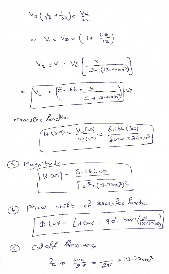
kindly solve part b, c ,d Q2: For the following high pass filter in Figure 2....
 kindly solve part b, c ,d
Q2: For the following high pass filter in Figure 2. Derive a formula for the gain or transfer function T (jw) = Find the condition of an optimal performance with minimum ripple in the passband. Find the cut-off frequency f3dB- Design this filter to have f3dB=100 Hz and maximum gain of 50. R3 nori Figure 2 w win V,
kindly solve part b, c ,d
Q2: For the following high pass filter in Figure 2. Derive a formula for the gain or transfer function T (jw) = Find the condition of an optimal performance with minimum ripple in the passband. Find the cut-off frequency f3dB- Design this filter to have f3dB=100 Hz and maximum gain of 50. R3 nori Figure 2 w win V,
Problem 2 a) Using 5 nF capacitors, design an active broad- band first-order bandreject filter with...
Problem 2 a) Using 5 nF capacitors, design an active broad- band first-order bandreject filter with a lower cutoff frequency of 1000 Hz, an upper cut-off frequency of 5000 Hz, and a pass band gain of 10dB. b) Draw the schematic diagram of the filter. c) Write the transfer function to find H(jωo), where ωo is the center frequency of the filter. d) What is the gain (in decibels) of the filer at the center frequency? e) Using Matlab make...
For the low-pass filter circuit shown in Fig 2 3k Ω 200mil in out Fig 2 3.a. Use a 2.2nF capacitor to design a high-pas...
 For the low-pass filter circuit shown in Fig 2 3k Ω 200mil in out Fig 2 3.a. Use a 2.2nF capacitor to design a high-pass filter to have a cutoff frequency of Skn Draw a schematic of your design. Show all component values and voltages c. Sketch the frequency response of the voltage gain and phase shift Magnitude dB Frequency Hz Phase Frequency Hz
For the low-pass filter circuit shown in Fig 2 3k Ω 200mil in out Fig 2...
For the low-pass filter circuit shown in Fig 2 3k Ω 200mil in out Fig 2 3.a. Use a 2.2nF capacitor to design a high-pass filter to have a cutoff frequency of Skn Draw a schematic of your design. Show all component values and voltages c. Sketch the frequency response of the voltage gain and phase shift Magnitude dB Frequency Hz Phase Frequency Hz
For the low-pass filter circuit shown in Fig 2 3k Ω 200mil in out Fig 2...
2- -Study the following high-pass filter circuit, find 5 nF t, 50 kΩ a-The cutoff requency...
 2- -Study the following high-pass filter circuit, find 5 nF t, 50 kΩ a-The cutoff requency in Hertz. b- The transfer function H(jw) @ f 200Hz
For the low-pass filter circuit shown in Fig 2 200mH 3k Ω out in Fig 2...
 For the low-pass filter circuit shown in Fig 2 200mH 3k Ω out in Fig 2 (i) (ii) (iii) Write an expression for the transfer function of the circuit State the value of the dc gain of the filter circuit in dB Calculate the cutoff frequency of the filter b. Sketch the frequency response of the voltage gain and phase shift for the filter shown in Fig 2. Show all the values and required information in both graphs Magnitude Frequency...
Problem 2 An RC circuit ( with an active component) has the following transfer function (where...
 Problem 2 An RC circuit ( with an active component) has the following transfer function (where R and Care positive) H(s) - Vout(8) _R|| R/10k12 Vin(8) 10KN 1 + $RC Where s = jw Find the value of the resistor and the value of the capacitor so that: for w = 0 rad/s, H(jw)lde = +12dB at f = 1kHz, |H(jw)lab = +9dB Problem 3 The transfer function of a circuit is given by H(S) = Vout(s) Vin(s) Where s...
Solve the next problems The next circuit allows signals to pass in a range from 12KHz...
 Solve the next problems
The next circuit allows signals to pass in a range from 12KHz to 20kHz. a) calculate the value of the components for all resistors use 10k b) draw the bode didgras C21 laset R1 u For the previous circuit, calculate the frequency range to be passed and the bandwidth gain in dB in R1 = 500l2, R2=30K2,01 = 100 nF and C2= 20 nF and: The filter shown below is used for a robotic manipulator to...
Solve the next problems
The next circuit allows signals to pass in a range from 12KHz to 20kHz. a) calculate the value of the components for all resistors use 10k b) draw the bode didgras C21 laset R1 u For the previous circuit, calculate the frequency range to be passed and the bandwidth gain in dB in R1 = 500l2, R2=30K2,01 = 100 nF and C2= 20 nF and: The filter shown below is used for a robotic manipulator to...
For each filter mentioned in the following cases, first simulate the circuit using Multisim. You can get a plot of the transfer function that is called the Bode plot. From the right toolbar, select &...
 For each filter mentioned in the following cases, first simulate the circuit using Multisim. You can get a plot of the transfer function that is called the Bode plot. From the right toolbar, select "Bode Plotter". Change initial (I) and final (F frequencies to 1Hz and 200 KHz, respectively. Use a Voltage AC source as the input signal. You do not need to change any parameter from voltage AC source Connect "Bode Plotter" to input and output of your circuit...
Simulation For each filter mentioned in the following cases, first simulate the circuit using Multisim. You can get a plot of the transfer function that is called the Bode plot. From the right toolba...
 Simulation For each filter mentioned in the following cases, first simulate the circuit using Multisim. You can get a plot of the transfer function that is called the Bode plot. From the right toolbar, select "Bode Plotter". Change initial (I) and final (F) frequencies to 1Hz and 200 KHz, respectively. Use a Voltage AC source as the input signal. You do not need to change any parameter from voltage AC source. Connect "Bode Plotter" to input and output of your...
 BPF Filter Bandpass Filter The following circuit acts as a C This filter has a center (resonance) frequency at Hz. 27-VLC and a 3-dB bandwidth of BW = Hz. 2RC 3l f, and a passband for which the signal is This means that the filter has 0 dB gain at attenuated less than 3 dB centered approximately at f, from f,-BW2 to f.+BW/2 (this passband is not exactly centered at f, but its total width is BW) 3l8 Input Signal...
 kindly solve part b, c ,d
Q2: For the following high pass filter in Figure 2. Derive a formula for the gain or transfer function T (jw) = Find the condition of an optimal performance with minimum ripple in the passband. Find the cut-off frequency f3dB- Design this filter to have f3dB=100 Hz and maximum gain of 50. R3 nori Figure 2 w win V,
kindly solve part b, c ,d
Q2: For the following high pass filter in Figure 2. Derive a formula for the gain or transfer function T (jw) = Find the condition of an optimal performance with minimum ripple in the passband. Find the cut-off frequency f3dB- Design this filter to have f3dB=100 Hz and maximum gain of 50. R3 nori Figure 2 w win V,
 For the low-pass filter circuit shown in Fig 2 3k Ω 200mil in out Fig 2 3.a. Use a 2.2nF capacitor to design a high-pass filter to have a cutoff frequency of Skn Draw a schematic of your design. Show all component values and voltages c. Sketch the frequency response of the voltage gain and phase shift Magnitude dB Frequency Hz Phase Frequency Hz
For the low-pass filter circuit shown in Fig 2 3k Ω 200mil in out Fig 2...
For the low-pass filter circuit shown in Fig 2 3k Ω 200mil in out Fig 2 3.a. Use a 2.2nF capacitor to design a high-pass filter to have a cutoff frequency of Skn Draw a schematic of your design. Show all component values and voltages c. Sketch the frequency response of the voltage gain and phase shift Magnitude dB Frequency Hz Phase Frequency Hz
For the low-pass filter circuit shown in Fig 2 3k Ω 200mil in out Fig 2...
 2- -Study the following high-pass filter circuit, find 5 nF t, 50 kΩ a-The cutoff requency in Hertz. b- The transfer function H(jw) @ f 200Hz
 For the low-pass filter circuit shown in Fig 2 200mH 3k Ω out in Fig 2 (i) (ii) (iii) Write an expression for the transfer function of the circuit State the value of the dc gain of the filter circuit in dB Calculate the cutoff frequency of the filter b. Sketch the frequency response of the voltage gain and phase shift for the filter shown in Fig 2. Show all the values and required information in both graphs Magnitude Frequency...
 Problem 2 An RC circuit ( with an active component) has the following transfer function (where R and Care positive) H(s) - Vout(8) _R|| R/10k12 Vin(8) 10KN 1 + $RC Where s = jw Find the value of the resistor and the value of the capacitor so that: for w = 0 rad/s, H(jw)lde = +12dB at f = 1kHz, |H(jw)lab = +9dB Problem 3 The transfer function of a circuit is given by H(S) = Vout(s) Vin(s) Where s...
 Solve the next problems
The next circuit allows signals to pass in a range from 12KHz to 20kHz. a) calculate the value of the components for all resistors use 10k b) draw the bode didgras C21 laset R1 u For the previous circuit, calculate the frequency range to be passed and the bandwidth gain in dB in R1 = 500l2, R2=30K2,01 = 100 nF and C2= 20 nF and: The filter shown below is used for a robotic manipulator to...
Solve the next problems
The next circuit allows signals to pass in a range from 12KHz to 20kHz. a) calculate the value of the components for all resistors use 10k b) draw the bode didgras C21 laset R1 u For the previous circuit, calculate the frequency range to be passed and the bandwidth gain in dB in R1 = 500l2, R2=30K2,01 = 100 nF and C2= 20 nF and: The filter shown below is used for a robotic manipulator to...
 For each filter mentioned in the following cases, first simulate the circuit using Multisim. You can get a plot of the transfer function that is called the Bode plot. From the right toolbar, select "Bode Plotter". Change initial (I) and final (F frequencies to 1Hz and 200 KHz, respectively. Use a Voltage AC source as the input signal. You do not need to change any parameter from voltage AC source Connect "Bode Plotter" to input and output of your circuit...
 Simulation For each filter mentioned in the following cases, first simulate the circuit using Multisim. You can get a plot of the transfer function that is called the Bode plot. From the right toolbar, select "Bode Plotter". Change initial (I) and final (F) frequencies to 1Hz and 200 KHz, respectively. Use a Voltage AC source as the input signal. You do not need to change any parameter from voltage AC source. Connect "Bode Plotter" to input and output of your...
Most questions answered within 3 hours.
-
Let x1, x2,x3,and x4 be a random sample from
population with normal distribution with mean ?...
asked 20 seconds from now -
A string of mass m and length L is under tension T. The speed of
a...
asked 4 minutes ago -
Look at the descriptions of high sensation seekers in your book.
They look like they would...
asked 4 minutes ago -
Write a method called is1to1 that accepts a map whose keys and
values are strings as...
asked 5 minutes ago -
In a study of self-medication, a simple random sample of 1230
adults completed a survey. The...
asked 15 minutes ago -
You ride a bicycle around on a circular track while
accelerating. The circle has a radius...
asked 12 minutes ago -
I am looking help with these 5 Questions, can you help me,
please
1) Ruth Hu...
asked 20 minutes ago -
Find the center of mass of the Eath-moon
system given:
Radius of Earth = 6.37x10^6
Radius...
asked 41 minutes ago -
Using the definition and measurement of GDP as a guide,
evaluate how the use of fiscal...
asked 24 minutes ago -
An overly optimistic sales budget may result in
a. increases in selling prices late in the...
asked 23 minutes ago -
Write a brief essay (300-500 words) that describes how a
country's economic growth can be measured...
asked 45 minutes ago -
16. For the following two
scenarios, describe whether the implied demand uncertainty would
increase, decrease or...
asked 38 minutes ago