
Homework Answers


Add Answer to:
-Design a synchronous counter using D FFs that has the following sequence: 000, 010, CBA 101,...
Design a synchronous counter that has the following sequence: 000, 010, 101, 110 and repeat. The...
Design a synchronous counter that has the following sequence: 000, 010, 101, 110 and repeat. The undesired states 001, 011, 100 and 111 must always go to 000 on the next clock pulse.
Design a Verilog model that describes the following state diagram. (Test bench and simulation are not required) 1. 01 10 1- 10 10 01 01 10 or 01) 01 Design a Verilog model that describes a synchr...
 Design a Verilog model that describes the following state diagram. (Test bench and simulation are not required) 1. 01 10 1- 10 10 01 01 10 or 01) 01 Design a Verilog model that describes a synchronous 3 bit counter. The counter has a counting mode control signal (M), when M-o, the counter counts up in the binary sequence, when M- 1, the counter advances through the Gray code sequence. (Test bench and simulation are required to verify the counter...
(4 pts) Write a behavioral Verilog module to implement a counter that counts in the following seq...
 Verilog! NOT VHDL Please
(4 pts) Write a behavioral Verilog module to implement a counter that counts in the following sequence: 000, 010, 100, 110, 001, 011, 101, 111, (repeat) 000, etc. Use a ROM and D flip-flops. Create a test bench for your counter design and run functional simulation in ModelSim.
(4 pts) Write a behavioral Verilog module to implement a counter that counts in the following sequence: 000, 010, 100, 110, 001, 011, 101, 111, (repeat) 000, etc....
Verilog! NOT VHDL Please
(4 pts) Write a behavioral Verilog module to implement a counter that counts in the following sequence: 000, 010, 100, 110, 001, 011, 101, 111, (repeat) 000, etc. Use a ROM and D flip-flops. Create a test bench for your counter design and run functional simulation in ModelSim.
(4 pts) Write a behavioral Verilog module to implement a counter that counts in the following sequence: 000, 010, 100, 110, 001, 011, 101, 111, (repeat) 000, etc....
Write a model of a counter which counts in the sequence mentioned below. The counter should...
Write a model of a counter which counts in the sequence mentioned below. The counter should use behavioral modeling andacase statement. Develop a testbench to test it.The testbench should display the counter output in the simulator console output. Simulate usingthe clock period of10 units for 200 ns. 000, 001, 011, 101, 111, 010, (repeat 000).The counter will have an enable signal (SW2), a reset signal (SW1), and a clock signal (SW15). The output of the counter will be on LED2-LED0.
Can anyone solve this? i dont understand? verilog 1. (30 pts) Design a mod-6 counter. A...
 Can anyone solve this? i dont understand? verilog
1. (30 pts) Design a mod-6 counter. A mod-6 counter updates its output per clock rising edge according to the following sequence: 000, 001, 010, 011, 100, 101 (then repeat the pattern....). en is enable control (synchronous high active), resetn is reset control (asynchronous low active signal to reset counting sequence to 000) Complete the following Verilog code: en module mod6(clock, resetn, en, z); zI2:0] clock resetn Endmodule
Can anyone solve this? i dont understand? verilog
1. (30 pts) Design a mod-6 counter. A mod-6 counter updates its output per clock rising edge according to the following sequence: 000, 001, 010, 011, 100, 101 (then repeat the pattern....). en is enable control (synchronous high active), resetn is reset control (asynchronous low active signal to reset counting sequence to 000) Complete the following Verilog code: en module mod6(clock, resetn, en, z); zI2:0] clock resetn Endmodule
Design a 8x4 ROM with the following contents. Address 000 001 010 011 100 101 110...
 Design a 8x4 ROM with the following contents. Address 000 001 010 011 100 101 110 111 ROM Data 0001 0001 0000 0000 0111 0110 1111 0101
Design a counter that counts in the following sequence: 010, 011, 100, 101, and repeat. Use JK flip-flops in your implementation.
Design a counter that counts in the following sequence: 010, 011, 100, 101, and repeat. Use JK flip-flops in your implementation.
Finite state machine (FSM) counter design: Gray codes have a useful property in that consecutive numbers differ in only a single bit position. Table 1 lists a 3-bit modulo 8 Gray code representing the...
 Finite state machine (FSM) counter design: Gray
codes have a useful property in that consecutive numbers differ in
only a single bit position. Table 1 lists a 3-bit modulo 8 Gray
code representing the numbers 0 to 7. Design a 3-bit modulo 8 Gray
code counter FSM.
a) First design and sketch a 3-bit modulo 8 Gray code counter
FSM with no inputs and three outputs, the 3-bit signal
Q2:0. (A modulo N counter counts from 0 to N −...
Finite state machine (FSM) counter design: Gray
codes have a useful property in that consecutive numbers differ in
only a single bit position. Table 1 lists a 3-bit modulo 8 Gray
code representing the numbers 0 to 7. Design a 3-bit modulo 8 Gray
code counter FSM.
a) First design and sketch a 3-bit modulo 8 Gray code counter
FSM with no inputs and three outputs, the 3-bit signal
Q2:0. (A modulo N counter counts from 0 to N −...
Instructor: Dr. A,Sctt 3. 130 pts. totall A "marching I's counter" outputs the following sequence in...
 Instructor: Dr. A,Sctt 3. 130 pts. totall A "marching I's counter" outputs the following sequence in decimal 0, 4,2, 1,0,... In The counter gets its name from the binary sequence, binary the sequence is 000, 100, 010, 001, 000, where it appears that the I's are marching from left to right when the clock cycles. Design the sequential circuit to produce the counter. Derive and draw a FSM state diagram [10 points) a. b. Using D fip lops,(), g(1), (o)...
Implement a synchronous sequential circuit to output the sequence 57315731 with an enable input (E) such...
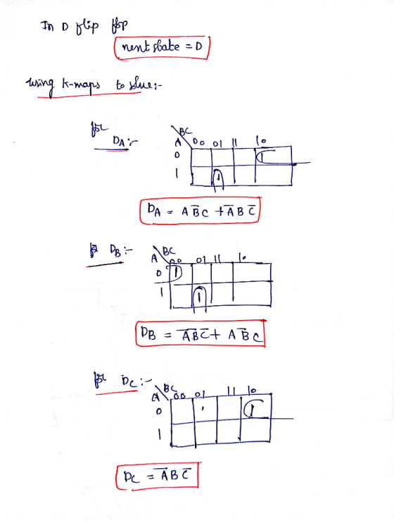
 Implement a synchronous sequential circuit to output the sequence 57315731 with an enable input (E) such Problem: P29 Integrated Circuits & Logic Design Student Code that the next digit in the sequence is output when - 1 and the current digit is output when E = 0. Implement this machine using D flip flops by using the truth table on this page and the K-maps on this and the following pages. Take advantage of any don't cares that come up....
 Design a Verilog model that describes the following state diagram. (Test bench and simulation are not required) 1. 01 10 1- 10 10 01 01 10 or 01) 01 Design a Verilog model that describes a synchronous 3 bit counter. The counter has a counting mode control signal (M), when M-o, the counter counts up in the binary sequence, when M- 1, the counter advances through the Gray code sequence. (Test bench and simulation are required to verify the counter...
 Verilog! NOT VHDL Please
(4 pts) Write a behavioral Verilog module to implement a counter that counts in the following sequence: 000, 010, 100, 110, 001, 011, 101, 111, (repeat) 000, etc. Use a ROM and D flip-flops. Create a test bench for your counter design and run functional simulation in ModelSim.
(4 pts) Write a behavioral Verilog module to implement a counter that counts in the following sequence: 000, 010, 100, 110, 001, 011, 101, 111, (repeat) 000, etc....
Verilog! NOT VHDL Please
(4 pts) Write a behavioral Verilog module to implement a counter that counts in the following sequence: 000, 010, 100, 110, 001, 011, 101, 111, (repeat) 000, etc. Use a ROM and D flip-flops. Create a test bench for your counter design and run functional simulation in ModelSim.
(4 pts) Write a behavioral Verilog module to implement a counter that counts in the following sequence: 000, 010, 100, 110, 001, 011, 101, 111, (repeat) 000, etc....
 Can anyone solve this? i dont understand? verilog
1. (30 pts) Design a mod-6 counter. A mod-6 counter updates its output per clock rising edge according to the following sequence: 000, 001, 010, 011, 100, 101 (then repeat the pattern....). en is enable control (synchronous high active), resetn is reset control (asynchronous low active signal to reset counting sequence to 000) Complete the following Verilog code: en module mod6(clock, resetn, en, z); zI2:0] clock resetn Endmodule
Can anyone solve this? i dont understand? verilog
1. (30 pts) Design a mod-6 counter. A mod-6 counter updates its output per clock rising edge according to the following sequence: 000, 001, 010, 011, 100, 101 (then repeat the pattern....). en is enable control (synchronous high active), resetn is reset control (asynchronous low active signal to reset counting sequence to 000) Complete the following Verilog code: en module mod6(clock, resetn, en, z); zI2:0] clock resetn Endmodule
 Design a 8x4 ROM with the following contents. Address 000 001 010 011 100 101 110 111 ROM Data 0001 0001 0000 0000 0111 0110 1111 0101
 Finite state machine (FSM) counter design: Gray
codes have a useful property in that consecutive numbers differ in
only a single bit position. Table 1 lists a 3-bit modulo 8 Gray
code representing the numbers 0 to 7. Design a 3-bit modulo 8 Gray
code counter FSM.
a) First design and sketch a 3-bit modulo 8 Gray code counter
FSM with no inputs and three outputs, the 3-bit signal
Q2:0. (A modulo N counter counts from 0 to N −...
Finite state machine (FSM) counter design: Gray
codes have a useful property in that consecutive numbers differ in
only a single bit position. Table 1 lists a 3-bit modulo 8 Gray
code representing the numbers 0 to 7. Design a 3-bit modulo 8 Gray
code counter FSM.
a) First design and sketch a 3-bit modulo 8 Gray code counter
FSM with no inputs and three outputs, the 3-bit signal
Q2:0. (A modulo N counter counts from 0 to N −...
 Instructor: Dr. A,Sctt 3. 130 pts. totall A "marching I's counter" outputs the following sequence in decimal 0, 4,2, 1,0,... In The counter gets its name from the binary sequence, binary the sequence is 000, 100, 010, 001, 000, where it appears that the I's are marching from left to right when the clock cycles. Design the sequential circuit to produce the counter. Derive and draw a FSM state diagram [10 points) a. b. Using D fip lops,(), g(1), (o)...
 Implement a synchronous sequential circuit to output the sequence 57315731 with an enable input (E) such Problem: P29 Integrated Circuits & Logic Design Student Code that the next digit in the sequence is output when - 1 and the current digit is output when E = 0. Implement this machine using D flip flops by using the truth table on this page and the K-maps on this and the following pages. Take advantage of any don't cares that come up....
Most questions answered within 3 hours.
-
Consider the following information:
Your company makes widgets. You are trying to figure out what
volume...
asked 20 seconds ago -
Recall that if X is a Student’s t random variable with n df,
then by definition...
asked 1 minute ago -
Math 333 Plz help ASAP
The yield of a chemical process is being studied. From previous...
asked 16 minutes ago -
Cobb-Douglas Preferences: Cobb-Douglas preferences on the
consump-
tion set R2+ can be represented by a utility...
asked 12 minutes ago -
In your experience, what are some of the barriers to the
successful implementation of a project?...
asked 15 minutes ago -
1. A normal distribution has a mean of
μ = 60 and a standard deviation
of...
asked 17 minutes ago -
The size of your Social Security benefits is determined by:
(select all that apply) Question 1...
asked 30 minutes ago -
Starch polymers are broken down by enzymes into monomers
called:
a.)maltose
b.) dextrins
c.) glucose
d.)...
asked 36 minutes ago -
How does HA (High Availability) work and name two ways it can
help an organization?
asked 39 minutes ago -
Saginaw Company is a garden products wholesale firm. In
December, Saginaw Company expects to sell 26,000...
asked 39 minutes ago -
Write a program for the management of a bookstore in java,
WITHOUT THE USE OF BOOK...
asked 39 minutes ago -
. Consider the Malthusian model and assume Y = zF (L; N) = zLN 1
,...
asked 52 minutes ago