
Homework Answers


Add Answer to:
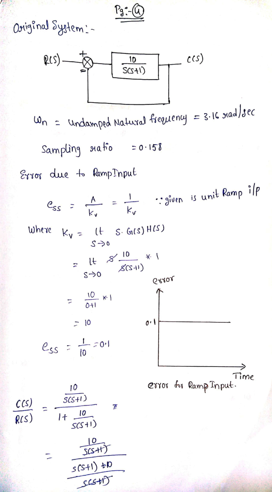
Problem Consider the system shown in Figure 5–74(a). The damping ratio of this system is 0.158...
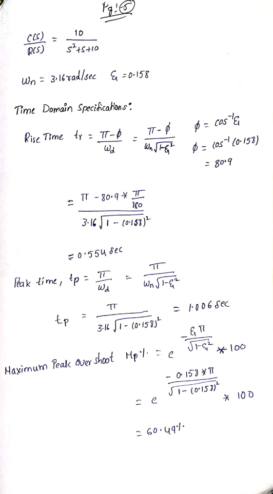
a) Consider the control system in Figure 2(a). Determine the transient response characteristics (rise time, peak...
 a) Consider the control system in Figure 2(a). Determine the transient response characteristics (rise time, peak time, maximum overshoot and settling time) and the steady state error for the system. (2 marks) b) To improve the relative stability, the tachometer feedback are employed as shown in Figure 2(b). i Determine the value K, so that the damping ratio of the system is 0.5. (1 % marks) ii. From the result obtained in (), evaluate the transient response characteristics (rise time,...
Question 2 a) Consider the control system in Figure 2(a). Determine the transient response characteristics (rise...
 Question 2 a) Consider the control system in Figure 2(a). Determine the transient response characteristics (rise time, peak time, maximum overshoot and settling time) and the steady state error for the system. (2 marks) b) To improve the relative stability, the tachometer feedback are employed as shown in Figure 2b). i Determine the value in so that the damping ratio of the system is 0.5. (1 % marks) From the result obtained in , evaluate the transient response characteristics (rise...
. a) Consider the control system in Figure 2(a). Determine the transient response characteristics (rise time,...
 .
a) Consider the control system in Figure 2(a). Determine the transient response characteristics (rise time, peak time, maximum overshoot and settling time) and the steady state error for the system. (2 marks) b) To improve the relative stability, the tachometer feedback are employed as shown in Figure 2(b). i. Determine the value Kn so that the damping ratio of the system is 0.5. (1 % marks) ii. From the result obtained in (), evaluate the transient response characteristics (rise...
.
a) Consider the control system in Figure 2(a). Determine the transient response characteristics (rise time, peak time, maximum overshoot and settling time) and the steady state error for the system. (2 marks) b) To improve the relative stability, the tachometer feedback are employed as shown in Figure 2(b). i. Determine the value Kn so that the damping ratio of the system is 0.5. (1 % marks) ii. From the result obtained in (), evaluate the transient response characteristics (rise...
Question 2 a) Consider the control system in Figure 2(a). Determine the transient response characteristics (rise...
 Question 2 a) Consider the control system in Figure 2(a). Determine the transient response characteristics (rise time, peak time, maximum overshoot and settling time) and the steady state error for the system. (2 marks) b) To improve the relative stability, the tachometer feedback are employed as shown in Figure 2(b). i Determine the value Kso that the damping ratio of the system is 0.5. (1 % marks) i. From the result obtained in (), evaluate the transient response characteristics (rise...
question 2 Question 2 a) Consider the control system in Figure 2(a). Determine the transient response...
 question 2
Question 2 a) Consider the control system in Figure 2(a). Determine the transient response characteristics (rise time, peak time, maximum overshoot and settling time) and the steady state error for the system (2 marks) b) To improve the relative stability, the tachometer feedback are employed as shown in Figure 2(b). Determine the value Kin so that the damping ratio of the system is 0.5. (1 % marks) it. From the result obtained in 0. evaluate the transient response...
question 2
Question 2 a) Consider the control system in Figure 2(a). Determine the transient response characteristics (rise time, peak time, maximum overshoot and settling time) and the steady state error for the system (2 marks) b) To improve the relative stability, the tachometer feedback are employed as shown in Figure 2(b). Determine the value Kin so that the damping ratio of the system is 0.5. (1 % marks) it. From the result obtained in 0. evaluate the transient response...
Question 2 a) Consider the control system in Figure 2(a). Determine the transient response characteristics (rise...
 Question 2 a) Consider the control system in Figure 2(a). Determine the transient response characteristics (rise time, peak time, maximum overshoot and settling time) and the steady state error for the system. (2 marks) b) To improve the relative stability, the tachometer feedback are employed as shown in Figure 2(b). Determine the value K, so that the damping ratio of the system is 0.5. (1 % marks) i. From the result obtained in (), evaluate the transient response characteristics (rise...
a) Consider the control system in Figure 2(a). Determine the transient response characteristics (rise time, peak...
 a) Consider the control system in Figure 2(a). Determine the transient response characteristics (rise time, peak time, maximum overshoot and settling time) and the steady state error for the system. (2 marks) b) To improve the relative stability, the tachometer feedback are employed as shown in Figure 2(b). i. Determine the value Kn so that the damping ratio of the system is 0.5. (1 22 marks) ii. iii. From the result obtained in (i), evaluate the transient response characteristics (rise...
Problem 1: Consider the block functional diagram of the satellite attitude control system shown in Figure...
 Problem 1: Consider the block functional diagram of the satellite attitude control system shown in Figure (a), here below. The output of this system exhibits continued oscillations and is not desirable. This system can be improved by using a tachometer feedback. Ki, as shown in Figure (b). Assuming that = 4, using block diagram algebra and theory of time performance specifications for second order systems, please, compute: (1) the value of the gain K such that closed loop transfer function...
Question 1 The natural frequency of the original system shown in Figure la is 12 rad/s....
 Question 1 The natural frequency of the original system shown in Figure la is 12 rad/s. In order to improve its transient response, a tachometer is to be added into the original system to yield damping ratio of 0.65. a) Calculate K and K2. b) Use Simulink to model the system (Unit-step input). c) Plot system responses (before and after adding the tachometer) and discuss how the system response is improved after adding the tachometer. Ris) + Preamplifier s(s+1) Power...
1. Consider the unity feedback system shown in figure 1 with G(S) -2sti a) Determine the...
 1. Consider the unity feedback system shown in figure 1 with G(S) -2sti a) Determine the closed loop transfer function TF(s) γ(s) R(s) What are the poles and zeros of TF1(s)? [2 marks] b) For TF(s), calculate the DC gain, natural frequency and damping ratio. Classify TF1(s) as underdamped overdamped, critically damped or undamped [3 marks] c) Use the initial value theorem and final value theorem to determine the initial value (Mo) and final value (M) of the [2 marks]...
 a) Consider the control system in Figure 2(a). Determine the transient response characteristics (rise time, peak time, maximum overshoot and settling time) and the steady state error for the system. (2 marks) b) To improve the relative stability, the tachometer feedback are employed as shown in Figure 2(b). i Determine the value K, so that the damping ratio of the system is 0.5. (1 % marks) ii. From the result obtained in (), evaluate the transient response characteristics (rise time,...
 Question 2 a) Consider the control system in Figure 2(a). Determine the transient response characteristics (rise time, peak time, maximum overshoot and settling time) and the steady state error for the system. (2 marks) b) To improve the relative stability, the tachometer feedback are employed as shown in Figure 2b). i Determine the value in so that the damping ratio of the system is 0.5. (1 % marks) From the result obtained in , evaluate the transient response characteristics (rise...
 .
a) Consider the control system in Figure 2(a). Determine the transient response characteristics (rise time, peak time, maximum overshoot and settling time) and the steady state error for the system. (2 marks) b) To improve the relative stability, the tachometer feedback are employed as shown in Figure 2(b). i. Determine the value Kn so that the damping ratio of the system is 0.5. (1 % marks) ii. From the result obtained in (), evaluate the transient response characteristics (rise...
.
a) Consider the control system in Figure 2(a). Determine the transient response characteristics (rise time, peak time, maximum overshoot and settling time) and the steady state error for the system. (2 marks) b) To improve the relative stability, the tachometer feedback are employed as shown in Figure 2(b). i. Determine the value Kn so that the damping ratio of the system is 0.5. (1 % marks) ii. From the result obtained in (), evaluate the transient response characteristics (rise...
 Question 2 a) Consider the control system in Figure 2(a). Determine the transient response characteristics (rise time, peak time, maximum overshoot and settling time) and the steady state error for the system. (2 marks) b) To improve the relative stability, the tachometer feedback are employed as shown in Figure 2(b). i Determine the value Kso that the damping ratio of the system is 0.5. (1 % marks) i. From the result obtained in (), evaluate the transient response characteristics (rise...
 question 2
Question 2 a) Consider the control system in Figure 2(a). Determine the transient response characteristics (rise time, peak time, maximum overshoot and settling time) and the steady state error for the system (2 marks) b) To improve the relative stability, the tachometer feedback are employed as shown in Figure 2(b). Determine the value Kin so that the damping ratio of the system is 0.5. (1 % marks) it. From the result obtained in 0. evaluate the transient response...
question 2
Question 2 a) Consider the control system in Figure 2(a). Determine the transient response characteristics (rise time, peak time, maximum overshoot and settling time) and the steady state error for the system (2 marks) b) To improve the relative stability, the tachometer feedback are employed as shown in Figure 2(b). Determine the value Kin so that the damping ratio of the system is 0.5. (1 % marks) it. From the result obtained in 0. evaluate the transient response...
 Question 2 a) Consider the control system in Figure 2(a). Determine the transient response characteristics (rise time, peak time, maximum overshoot and settling time) and the steady state error for the system. (2 marks) b) To improve the relative stability, the tachometer feedback are employed as shown in Figure 2(b). Determine the value K, so that the damping ratio of the system is 0.5. (1 % marks) i. From the result obtained in (), evaluate the transient response characteristics (rise...
 a) Consider the control system in Figure 2(a). Determine the transient response characteristics (rise time, peak time, maximum overshoot and settling time) and the steady state error for the system. (2 marks) b) To improve the relative stability, the tachometer feedback are employed as shown in Figure 2(b). i. Determine the value Kn so that the damping ratio of the system is 0.5. (1 22 marks) ii. iii. From the result obtained in (i), evaluate the transient response characteristics (rise...
 Problem 1: Consider the block functional diagram of the satellite attitude control system shown in Figure (a), here below. The output of this system exhibits continued oscillations and is not desirable. This system can be improved by using a tachometer feedback. Ki, as shown in Figure (b). Assuming that = 4, using block diagram algebra and theory of time performance specifications for second order systems, please, compute: (1) the value of the gain K such that closed loop transfer function...
 Question 1 The natural frequency of the original system shown in Figure la is 12 rad/s. In order to improve its transient response, a tachometer is to be added into the original system to yield damping ratio of 0.65. a) Calculate K and K2. b) Use Simulink to model the system (Unit-step input). c) Plot system responses (before and after adding the tachometer) and discuss how the system response is improved after adding the tachometer. Ris) + Preamplifier s(s+1) Power...
 1. Consider the unity feedback system shown in figure 1 with G(S) -2sti a) Determine the closed loop transfer function TF(s) γ(s) R(s) What are the poles and zeros of TF1(s)? [2 marks] b) For TF(s), calculate the DC gain, natural frequency and damping ratio. Classify TF1(s) as underdamped overdamped, critically damped or undamped [3 marks] c) Use the initial value theorem and final value theorem to determine the initial value (Mo) and final value (M) of the [2 marks]...
Most questions answered within 3 hours.
-
Describe two obstacles that makes fixing atmospheric nitrogen
difficult.
asked 1 second ago -
T
F 53) Most differences
between human groups are the result of biology rather than
culture....
asked 4 minutes ago -
A 5.20 mW helium neon laser emits a visible laser beam with a
wavelength of 633...
asked 7 minutes ago -
Assignment:
Your
organization has made a strategic decision
to
outsourcework
currently performed in house. You have...
asked 6 minutes ago -
A hospital performs 100 surgeries per week. The probability that
complications after surgery occur is 10%....
asked 7 minutes ago -
In preparing its cash flow statement for the year ended December
31, 2018, Green Co. gathered...
asked 8 minutes ago -
Donna is 18 years old and full time accounting student.She is
saving for an overseas holiday...
asked 9 minutes ago -
Service-oriented architectures (SOA) provide
object-oriented architectures for web platforms that represent a
collection of services. SOA...
asked 9 minutes ago -
Le Terroir Winery is considering an expansion project to produce
fine wines. The trial expansion will...
asked 18 minutes ago -
The Bahraini public budget experiences deficit in the last
seven years, what are procedures are taken...
asked 25 minutes ago -
You invested $30,000 in a mutual fund at the beginning of the
year when the NAV...
asked 29 minutes ago -
Would you expect the price elasticity of supply for guitars to
be more inelastic in the...
asked 31 minutes ago