


Homework Answers
Do rate


Add Answer to:
- P12.44 Figure P12.44 shows Mohr's circle for a point in a phys- ical object that...
Q5: 10-56 Determine the principal stresses and the maximum shear stress using Mohr's circle. The following...
 Q5: 10-56 Determine the principal stresses and the maximum shear stress using Mohr's circle. The following data sets give the stresses on the initial stress element (ox=300 MPa; Oy=-100 MPa; Txy=80MPa CW). Perform the following operations: (a) Draw the complete Mohr's circle, labeling critical points including 01, 02, Tmax, and Oavg. (b) On Mohr's circle, indicate which line represents the x-axis on the initial stress element. (c) On Mohr's circle, indicate the angles from the line representing the x-axis to...
Homework For each of the plane stress states listed below, draw a Mohr's circle diagram properly...
 Homework For each of the plane stress states listed below, draw a Mohr's circle diagram properly labeled, find the principal normal and shear stresses, and determine the angle from the x axis to 0. Draw stress elements as in Fig. 3-11c and d and label all details. (a) Ox = -8 MPa, Oy = 7 MPa, Txy = 6 MPa cw (b) 0x = 9 MPa, Oy = -6 MPa, Txy = 3 MPa cw (C) Ox = -4 MPa,...
Consider a point in a structural member that is subjected to plane stress. Normal and shear...
 Consider a point in a structural member that is subjected to plane stress. Normal and shear stress magnitudes acting on horizontal and vertical planes at the point are Sx = 95.3 MPa, Sy = 79.3 MPa, and Sxy = 41.0 MPa. (a) Determine the principal stresses and the maximum in-plane shear stress acting at the point. (b) On your paper show these stresses in an appropriate sketch (e.g., see Figure 12.15 or Figure 12.16). (c) Compute the absolute maximum shear...
The cantilever beam shown in the figure is subjected to a concentrated load at point B....
 The cantilever beam shown in the figure is subjected to a concentrated load at point B. The stresses acting at point H on the beam are to be determined. H Cross section For this analysis, use the following values: Beam and Load. a = 1.75 m b=0.30 m @= 60 degrees P = 25 KN Cross-sectional Dimensions d=250 mm bp = 125 mm ty=7 mm tw = 7 mm C= 30 mm (Note: The load P applied at Bacts in...
Problem 1 - Mohr's circle for plane stress For the given state of stress,[30 complete following:...
 Problem 1 - Mohr's circle for plane stress For the given state of stress,[30 complete following: pts. 1. Draw Mohr's circle showing the principal stresses (max & min), center points (C) and radius R. (20 pts.] 60 MPa 180 MPa NMP MPa 2. Determine the principal planes (20and ) and the maximum in-plane shear stress (max). What is the corresponding normal stress (O") for this maximum in-plane shear stress? [10 pts.)
The cantilever beam shown in the figure is subjected to a concentrated load at point B....
 The cantilever beam shown in the figure is subjected to a concentrated load at point B. The stresses acting at point Hon the beam are to be determined Ques! Text- Quest Text Ent T Quest Text End Cross section Viewir Text-Ent For this analysis, use the following values Beam and Load. Questi Muitstep a. 1.75 m b-0.30 m 0.63 degrees P.49 KN Questid Text Entry Questio Text Entry Cross-sectional Dimensions d - 275 mm by - 150 mm - 13...
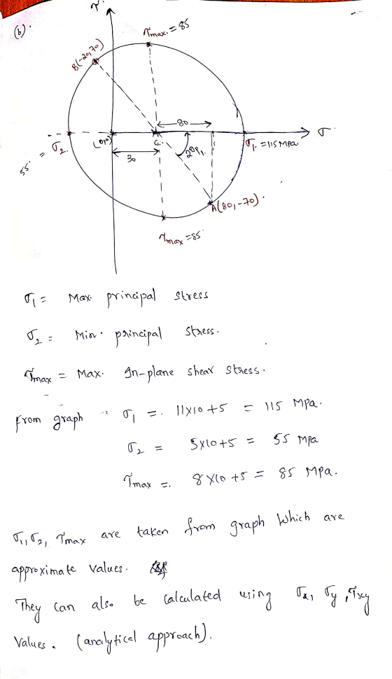
Using Mohr's circle determine for the below differential element: a) the principal stresses and the plan...
 Using Mohr's circle determine for the below differential
element:
a) the principal stresses and the plan on which they act. Show
the stresses on a properly oriented differential element. Label all
stresses.
b) the maximum shear stress and the plan on which they act. Show
the stresses on a properly oriented differential element. Label all
stresses.
c) the stresses on a differential element 40 degrees clockwise
from the original element. Show the stresses on a properly oriented
differential element. Label...
Using Mohr's circle determine for the below differential
element:
a) the principal stresses and the plan on which they act. Show
the stresses on a properly oriented differential element. Label all
stresses.
b) the maximum shear stress and the plan on which they act. Show
the stresses on a properly oriented differential element. Label all
stresses.
c) the stresses on a differential element 40 degrees clockwise
from the original element. Show the stresses on a properly oriented
differential element. Label...
SX= 204MPa SY= -12MPa 2. Figure 2 shows a tubular joint subjected to moment M and...
 SX= 204MPa
SY= -12MPa
2. Figure 2 shows a tubular joint subjected to moment M and P. Due to these CLO4 loads, an element of the joint in xy plane ABCD has stress system shown in Figure 3. The values of the stresses are Oxx = SX , Oyy = SY, and Txy = 45 MPa. The values and units of measure for the stresses are as given in the data sheet. Construct Mohr's circle for the stress systems to...
SX= 204MPa
SY= -12MPa
2. Figure 2 shows a tubular joint subjected to moment M and P. Due to these CLO4 loads, an element of the joint in xy plane ABCD has stress system shown in Figure 3. The values of the stresses are Oxx = SX , Oyy = SY, and Txy = 45 MPa. The values and units of measure for the stresses are as given in the data sheet. Construct Mohr's circle for the stress systems to...
Part A - Normal Stresses, Shear, and Angles The stress element shown in the figure below...
 Part A - Normal Stresses, Shear, and Angles The stress element shown in the figure below is subjected to the indicated stresses of magnitude 0,1 = 35 MPa, oyl = 57 MPa, and Tryl = 41 MPa Oy Txy Determine the principal normal stresses 01 and 02, the maximum in-plane shear stress Tmax,in-plane, and the angles at which they occur relative to the given stress element. Follow the sign convention. Suppose that when the element is oriented at an angle...
3. Figure shows a state of plane stress consists of normal stresses 60 MPa and Ly-40MPa;...
 3. Figure shows a state of plane stress consists of normal stresses 60 MPa and Ly-40MPa; and unknown shear stress, The maximum principal stress was determined to be 104.34 MPa. Using Mohr's cirdle, determine a. the magnitude of the shear stress, b. the principal plane and the minimum principal stress. Then, sketch the element showing all stresses in its proper orientation, c. the maximum shear stress, associated normal stress and the orientation of the element. Then, sketch the element showing...
 Q5: 10-56 Determine the principal stresses and the maximum shear stress using Mohr's circle. The following data sets give the stresses on the initial stress element (ox=300 MPa; Oy=-100 MPa; Txy=80MPa CW). Perform the following operations: (a) Draw the complete Mohr's circle, labeling critical points including 01, 02, Tmax, and Oavg. (b) On Mohr's circle, indicate which line represents the x-axis on the initial stress element. (c) On Mohr's circle, indicate the angles from the line representing the x-axis to...
 Homework For each of the plane stress states listed below, draw a Mohr's circle diagram properly labeled, find the principal normal and shear stresses, and determine the angle from the x axis to 0. Draw stress elements as in Fig. 3-11c and d and label all details. (a) Ox = -8 MPa, Oy = 7 MPa, Txy = 6 MPa cw (b) 0x = 9 MPa, Oy = -6 MPa, Txy = 3 MPa cw (C) Ox = -4 MPa,...
 Consider a point in a structural member that is subjected to plane stress. Normal and shear stress magnitudes acting on horizontal and vertical planes at the point are Sx = 95.3 MPa, Sy = 79.3 MPa, and Sxy = 41.0 MPa. (a) Determine the principal stresses and the maximum in-plane shear stress acting at the point. (b) On your paper show these stresses in an appropriate sketch (e.g., see Figure 12.15 or Figure 12.16). (c) Compute the absolute maximum shear...
 The cantilever beam shown in the figure is subjected to a concentrated load at point B. The stresses acting at point H on the beam are to be determined. H Cross section For this analysis, use the following values: Beam and Load. a = 1.75 m b=0.30 m @= 60 degrees P = 25 KN Cross-sectional Dimensions d=250 mm bp = 125 mm ty=7 mm tw = 7 mm C= 30 mm (Note: The load P applied at Bacts in...
 Problem 1 - Mohr's circle for plane stress For the given state of stress,[30 complete following: pts. 1. Draw Mohr's circle showing the principal stresses (max & min), center points (C) and radius R. (20 pts.] 60 MPa 180 MPa NMP MPa 2. Determine the principal planes (20and ) and the maximum in-plane shear stress (max). What is the corresponding normal stress (O") for this maximum in-plane shear stress? [10 pts.)
 The cantilever beam shown in the figure is subjected to a concentrated load at point B. The stresses acting at point Hon the beam are to be determined Ques! Text- Quest Text Ent T Quest Text End Cross section Viewir Text-Ent For this analysis, use the following values Beam and Load. Questi Muitstep a. 1.75 m b-0.30 m 0.63 degrees P.49 KN Questid Text Entry Questio Text Entry Cross-sectional Dimensions d - 275 mm by - 150 mm - 13...
 Using Mohr's circle determine for the below differential
element:
a) the principal stresses and the plan on which they act. Show
the stresses on a properly oriented differential element. Label all
stresses.
b) the maximum shear stress and the plan on which they act. Show
the stresses on a properly oriented differential element. Label all
stresses.
c) the stresses on a differential element 40 degrees clockwise
from the original element. Show the stresses on a properly oriented
differential element. Label...
Using Mohr's circle determine for the below differential
element:
a) the principal stresses and the plan on which they act. Show
the stresses on a properly oriented differential element. Label all
stresses.
b) the maximum shear stress and the plan on which they act. Show
the stresses on a properly oriented differential element. Label all
stresses.
c) the stresses on a differential element 40 degrees clockwise
from the original element. Show the stresses on a properly oriented
differential element. Label...
 SX= 204MPa
SY= -12MPa
2. Figure 2 shows a tubular joint subjected to moment M and P. Due to these CLO4 loads, an element of the joint in xy plane ABCD has stress system shown in Figure 3. The values of the stresses are Oxx = SX , Oyy = SY, and Txy = 45 MPa. The values and units of measure for the stresses are as given in the data sheet. Construct Mohr's circle for the stress systems to...
SX= 204MPa
SY= -12MPa
2. Figure 2 shows a tubular joint subjected to moment M and P. Due to these CLO4 loads, an element of the joint in xy plane ABCD has stress system shown in Figure 3. The values of the stresses are Oxx = SX , Oyy = SY, and Txy = 45 MPa. The values and units of measure for the stresses are as given in the data sheet. Construct Mohr's circle for the stress systems to...
 Part A - Normal Stresses, Shear, and Angles The stress element shown in the figure below is subjected to the indicated stresses of magnitude 0,1 = 35 MPa, oyl = 57 MPa, and Tryl = 41 MPa Oy Txy Determine the principal normal stresses 01 and 02, the maximum in-plane shear stress Tmax,in-plane, and the angles at which they occur relative to the given stress element. Follow the sign convention. Suppose that when the element is oriented at an angle...
 3. Figure shows a state of plane stress consists of normal stresses 60 MPa and Ly-40MPa; and unknown shear stress, The maximum principal stress was determined to be 104.34 MPa. Using Mohr's cirdle, determine a. the magnitude of the shear stress, b. the principal plane and the minimum principal stress. Then, sketch the element showing all stresses in its proper orientation, c. the maximum shear stress, associated normal stress and the orientation of the element. Then, sketch the element showing...
Most questions answered within 3 hours.
-
Explain in detail
Germany is the fifth largest economy
explain what goods and services Germany specializes...
asked 10 minutes ago -
The density of platinum is 21.45 g/mL. If a cube of platinum
with a mass of...
asked 15 minutes ago -
Accounts Receivable
Sales
A/R Posting
Extended Sales Invoice
Packing Slip
Compare invoice to packing slip 2...
asked 18 minutes ago -
Michaella, age 23, is a full-time law student and is claimed by
her parents as a...
asked 18 minutes ago -
Why are polymers not typically casted into products?
asked 35 minutes ago -
When rolling a die 129 times, what is the probability of rolling
a 6 no more...
asked 52 minutes ago -
4. A call option currently sells for $7.75. It has a strike
price of $85 and...
asked 41 minutes ago -
1.
You need to prepare 10.0 liters of an acid aqueous solution with a
pH of...
asked 44 minutes ago -
Along an aggregate supply curve, if the level of output is less
than the natural level...
asked 44 minutes ago -
By 2025, annual consumption in emerging markets will total $30
trillion and contribute more than ________...
asked 49 minutes ago -
At what point does reformation cease to be a viable option for
those who are oppressed...
asked 53 minutes ago -
Place letters corresponding to amounts in the proper order for
lightest to heaviest samples:
a) 2100...
asked 58 minutes ago