

Homework Answers


the blue color signal is voltage across current source which is not as expected since the inductor is connectoed parellel to it as from the theory of inductors chande in curren is not acceptable it it hppens votage across it reduces.
that is why voltages as lesses than as expected.
green colour signal is voltage across 500 ohm ( V0)
b)
from the simulation we found that 24usec of time is taken Vo to follow ig.
Add Answer to:
Need only in LT SPICE:
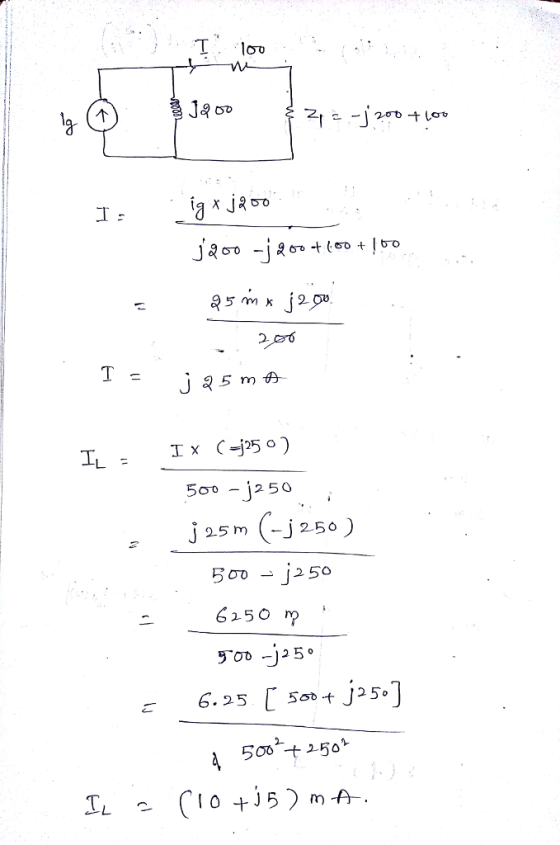
2. Electric Circuits (10th Edition: Redo Problem 9.31 use SPICE simulation...
Please help with the LT SPICE for this nmos transistor analysis problem. I figured out the calcul...
 please help with the LT SPICE for this nmos transistor analysis
problem. I figured out the calculations, I just need help verifying
them with LT SPICE. thank you!
Analyze the following MOSFET circuit for dc bias. Solve for ID, VGs and VDs Use RD-5 kQ, Rs-5 kQ, RG,-1 ΜΩ and RG2-1 MS2. Use a power supply with VDD-| 2 V and K.-I mA/V2 and Vin-1 V. RG RD RG2 Rs Verify the analysis of the circuit of Prob. 5 by...
please help with the LT SPICE for this nmos transistor analysis
problem. I figured out the calculations, I just need help verifying
them with LT SPICE. thank you!
Analyze the following MOSFET circuit for dc bias. Solve for ID, VGs and VDs Use RD-5 kQ, Rs-5 kQ, RG,-1 ΜΩ and RG2-1 MS2. Use a power supply with VDD-| 2 V and K.-I mA/V2 and Vin-1 V. RG RD RG2 Rs Verify the analysis of the circuit of Prob. 5 by...
Problem 1: BJT DC Circuits Analyze the four circuits below, first analytically and then verify us...
 Problem 1: BJT DC Circuits Analyze the four circuits below, first analytically and then verify using simulations in PSPICE/Multisim. You have to solve each circuit that is, find the status of the BUT (active, saturation or cutoff mode) and then find all the node voltages and all the currents. Whenever you solve manually always make the following assumptions: for npn BIT VE-0.7V (if the BE junction is forward biased) for pap BIT VEB-0.7V (if the BE junction is forward biased)...
Logic Circuits Lab Project ELEG 3021 2018 Fall Obiective: Given a practical problem, using the knowledge...
 Logic Circuits Lab Project ELEG 3021 2018 Fall Obiective: Given a practical problem, using the knowledge learned in Logic Circuit class and practical skills gained in the Logic Circuit Lab, develop and conduct appropriate experimentation, analyze and interpret data, and use engineering judgment to draw conclusions. Problem: Given any two unsigned 4-bit numbers A (AsA2AiAo) and B (B;B B Bo), please compare the magnitude of this two numbers and pass the larger one of the two to the output Y...
need help with b,c,d,e Course Home <Ch 31: Electric Circuits Problem 31.55 In the the circuit...
 need help with b,c,d,e
Course Home <Ch 31: Electric Circuits Problem 31.55 In the the circuit in Floure 1) R = 400 A. R 900 R R 200 and E. 15 V. The electric potential at location d is defined to be because the negative terminal of the battery latached to ground What is the equivalent resistance of the circuit in the figure? Express your answer with the appropriate units. R = 15000 Previous Answers Figure 1 of 1 All...
need help with b,c,d,e
Course Home <Ch 31: Electric Circuits Problem 31.55 In the the circuit in Floure 1) R = 400 A. R 900 R R 200 and E. 15 V. The electric potential at location d is defined to be because the negative terminal of the battery latached to ground What is the equivalent resistance of the circuit in the figure? Express your answer with the appropriate units. R = 15000 Previous Answers Figure 1 of 1 All...
Complete the lab 5 SERIES CIRCUITS VW REFERENCE READING Principles of Electric Circuits: Sectang 81 through...
 Complete the lab 5
SERIES CIRCUITS VW REFERENCE READING Principles of Electric Circuits: Sectang 81 through 6-4. RELATED PROBLEMS FROM PRINCIPLES OF ELECTRIC CIRCUITS Chapter 5, Problems 1 through 26. OBJECTIVE To verify that the total resistance in a series-connected circuit is the sum of the individual resistances. EQUIPMENT dc power supply 0-10 V DMM or VOM Resistors (+5%): 110 2k12 322 3.9 kn 6.1 kn BACKGROUND When resistors are connected in series, the current that will flow is calculated...
Complete the lab 5
SERIES CIRCUITS VW REFERENCE READING Principles of Electric Circuits: Sectang 81 through 6-4. RELATED PROBLEMS FROM PRINCIPLES OF ELECTRIC CIRCUITS Chapter 5, Problems 1 through 26. OBJECTIVE To verify that the total resistance in a series-connected circuit is the sum of the individual resistances. EQUIPMENT dc power supply 0-10 V DMM or VOM Resistors (+5%): 110 2k12 322 3.9 kn 6.1 kn BACKGROUND When resistors are connected in series, the current that will flow is calculated...
Only need the last question 5 thanks! 3) RLC Parallel Circuits: Differential Equations and Laplace U2...
 Only need the last question 5 thanks!
3) RLC Parallel Circuits: Differential Equations and Laplace U2 U1 TOPEN 0 TCLOSE 0 L1 R1 0.15H C1 2E-8F 11 10E-3 2 10E-3 At t 0, U1 closes and U2 opens. 3.1: What is the intial (t-0+) current through the capacitor? What is the initial (t=0+) voltage across the capacitor? 3.2: What is the DC steady state current though the capacitor ast goes to infinity? 3.3: Find the current through the CAPACITOR as...
Only need the last question 5 thanks!
3) RLC Parallel Circuits: Differential Equations and Laplace U2 U1 TOPEN 0 TCLOSE 0 L1 R1 0.15H C1 2E-8F 11 10E-3 2 10E-3 At t 0, U1 closes and U2 opens. 3.1: What is the intial (t-0+) current through the capacitor? What is the initial (t=0+) voltage across the capacitor? 3.2: What is the DC steady state current though the capacitor ast goes to infinity? 3.3: Find the current through the CAPACITOR as...
PLEASE SHOW ALL WORK AND TO FOLLOW DIRECTIONS. PLEASE USE PSPICE. STUDENT ID= 7220849 3. Using...
 PLEASE SHOW ALL WORK AND TO FOLLOW DIRECTIONS. PLEASE USE
PSPICE.
STUDENT ID= 7220849
3. Using a DC Sweep analysis to graph currents and voltages Let R1 through R4 equivalent to the digits 1 through 4 in your StudentID in k 2 (use 10 k12 for a digit of 0). • For example, if your StudentID is 9870654 then R1 =9 KS2, R2 =8 kN, R3 = 7k2 and R4 = 10k12 A. Analyze Circuit 3 by hand to determine...
PLEASE SHOW ALL WORK AND TO FOLLOW DIRECTIONS. PLEASE USE
PSPICE.
STUDENT ID= 7220849
3. Using a DC Sweep analysis to graph currents and voltages Let R1 through R4 equivalent to the digits 1 through 4 in your StudentID in k 2 (use 10 k12 for a digit of 0). • For example, if your StudentID is 9870654 then R1 =9 KS2, R2 =8 kN, R3 = 7k2 and R4 = 10k12 A. Analyze Circuit 3 by hand to determine...
can anyone help with this? R1 R3 IkΩ 1kΩ. R2 2kQ R4 510 E1 9V V1...
 can anyone help with this?
R1 R3 IkΩ 1kΩ. R2 2kQ R4 510 E1 9V V1 V3 R1 R3 A1 A3 1k2 lkQ A2 A4 SR2 SR4 510 2 V4 V2 9V E1 2kn tho reltago VE across the battery in the appropriate column of Item W Item-3: Pspice L Build your circuit in Orcad Pspice and measure the appropriate voltages and currents in the simulation. Some values may need to be interpreted from the simulation results (such as the...
can anyone help with this?
R1 R3 IkΩ 1kΩ. R2 2kQ R4 510 E1 9V V1 V3 R1 R3 A1 A3 1k2 lkQ A2 A4 SR2 SR4 510 2 V4 V2 9V E1 2kn tho reltago VE across the battery in the appropriate column of Item W Item-3: Pspice L Build your circuit in Orcad Pspice and measure the appropriate voltages and currents in the simulation. Some values may need to be interpreted from the simulation results (such as the...
DOING NUMBER 7 of VHDL lab "write your own full-adder in VHDL " is my only...
 DOING NUMBER 7 of VHDL lab "write your own full-adder in
VHDL " is my only request. Do the rest, if you have
time.
To verify and apply techniques to build half adders and full adder to perform additions using gates. For each part of the procedure, show the number of that section and include a logic diagram of the circuit, truth table for the circuit, and any other necessary information. Adder Implementation 1. Construct a binary half-adder and record...
DOING NUMBER 7 of VHDL lab "write your own full-adder in
VHDL " is my only request. Do the rest, if you have
time.
To verify and apply techniques to build half adders and full adder to perform additions using gates. For each part of the procedure, show the number of that section and include a logic diagram of the circuit, truth table for the circuit, and any other necessary information. Adder Implementation 1. Construct a binary half-adder and record...
Learning Goal: To use the node-voltage method to solve circuits with branches containing only a voltage...
 Learning Goal: To use the node-voltage method to solve circuits with branches containing only a voltage source. The node-voltage method is a general technique for solving circuits. Fundamentally, it involves writing KCL equations at essential nodes. When the circuit contains a dependent source, you must write a constraint equation for each dependent source, in addition to the KCL equations. When the circuit contains one or more voltage sources that are the only components in branches connecting two essential nodes, the...
 please help with the LT SPICE for this nmos transistor analysis
problem. I figured out the calculations, I just need help verifying
them with LT SPICE. thank you!
Analyze the following MOSFET circuit for dc bias. Solve for ID, VGs and VDs Use RD-5 kQ, Rs-5 kQ, RG,-1 ΜΩ and RG2-1 MS2. Use a power supply with VDD-| 2 V and K.-I mA/V2 and Vin-1 V. RG RD RG2 Rs Verify the analysis of the circuit of Prob. 5 by...
please help with the LT SPICE for this nmos transistor analysis
problem. I figured out the calculations, I just need help verifying
them with LT SPICE. thank you!
Analyze the following MOSFET circuit for dc bias. Solve for ID, VGs and VDs Use RD-5 kQ, Rs-5 kQ, RG,-1 ΜΩ and RG2-1 MS2. Use a power supply with VDD-| 2 V and K.-I mA/V2 and Vin-1 V. RG RD RG2 Rs Verify the analysis of the circuit of Prob. 5 by...
 Problem 1: BJT DC Circuits Analyze the four circuits below, first analytically and then verify using simulations in PSPICE/Multisim. You have to solve each circuit that is, find the status of the BUT (active, saturation or cutoff mode) and then find all the node voltages and all the currents. Whenever you solve manually always make the following assumptions: for npn BIT VE-0.7V (if the BE junction is forward biased) for pap BIT VEB-0.7V (if the BE junction is forward biased)...
 Logic Circuits Lab Project ELEG 3021 2018 Fall Obiective: Given a practical problem, using the knowledge learned in Logic Circuit class and practical skills gained in the Logic Circuit Lab, develop and conduct appropriate experimentation, analyze and interpret data, and use engineering judgment to draw conclusions. Problem: Given any two unsigned 4-bit numbers A (AsA2AiAo) and B (B;B B Bo), please compare the magnitude of this two numbers and pass the larger one of the two to the output Y...
 need help with b,c,d,e
Course Home <Ch 31: Electric Circuits Problem 31.55 In the the circuit in Floure 1) R = 400 A. R 900 R R 200 and E. 15 V. The electric potential at location d is defined to be because the negative terminal of the battery latached to ground What is the equivalent resistance of the circuit in the figure? Express your answer with the appropriate units. R = 15000 Previous Answers Figure 1 of 1 All...
need help with b,c,d,e
Course Home <Ch 31: Electric Circuits Problem 31.55 In the the circuit in Floure 1) R = 400 A. R 900 R R 200 and E. 15 V. The electric potential at location d is defined to be because the negative terminal of the battery latached to ground What is the equivalent resistance of the circuit in the figure? Express your answer with the appropriate units. R = 15000 Previous Answers Figure 1 of 1 All...
 Complete the lab 5
SERIES CIRCUITS VW REFERENCE READING Principles of Electric Circuits: Sectang 81 through 6-4. RELATED PROBLEMS FROM PRINCIPLES OF ELECTRIC CIRCUITS Chapter 5, Problems 1 through 26. OBJECTIVE To verify that the total resistance in a series-connected circuit is the sum of the individual resistances. EQUIPMENT dc power supply 0-10 V DMM or VOM Resistors (+5%): 110 2k12 322 3.9 kn 6.1 kn BACKGROUND When resistors are connected in series, the current that will flow is calculated...
Complete the lab 5
SERIES CIRCUITS VW REFERENCE READING Principles of Electric Circuits: Sectang 81 through 6-4. RELATED PROBLEMS FROM PRINCIPLES OF ELECTRIC CIRCUITS Chapter 5, Problems 1 through 26. OBJECTIVE To verify that the total resistance in a series-connected circuit is the sum of the individual resistances. EQUIPMENT dc power supply 0-10 V DMM or VOM Resistors (+5%): 110 2k12 322 3.9 kn 6.1 kn BACKGROUND When resistors are connected in series, the current that will flow is calculated...
 Only need the last question 5 thanks!
3) RLC Parallel Circuits: Differential Equations and Laplace U2 U1 TOPEN 0 TCLOSE 0 L1 R1 0.15H C1 2E-8F 11 10E-3 2 10E-3 At t 0, U1 closes and U2 opens. 3.1: What is the intial (t-0+) current through the capacitor? What is the initial (t=0+) voltage across the capacitor? 3.2: What is the DC steady state current though the capacitor ast goes to infinity? 3.3: Find the current through the CAPACITOR as...
Only need the last question 5 thanks!
3) RLC Parallel Circuits: Differential Equations and Laplace U2 U1 TOPEN 0 TCLOSE 0 L1 R1 0.15H C1 2E-8F 11 10E-3 2 10E-3 At t 0, U1 closes and U2 opens. 3.1: What is the intial (t-0+) current through the capacitor? What is the initial (t=0+) voltage across the capacitor? 3.2: What is the DC steady state current though the capacitor ast goes to infinity? 3.3: Find the current through the CAPACITOR as...
 PLEASE SHOW ALL WORK AND TO FOLLOW DIRECTIONS. PLEASE USE
PSPICE.
STUDENT ID= 7220849
3. Using a DC Sweep analysis to graph currents and voltages Let R1 through R4 equivalent to the digits 1 through 4 in your StudentID in k 2 (use 10 k12 for a digit of 0). • For example, if your StudentID is 9870654 then R1 =9 KS2, R2 =8 kN, R3 = 7k2 and R4 = 10k12 A. Analyze Circuit 3 by hand to determine...
PLEASE SHOW ALL WORK AND TO FOLLOW DIRECTIONS. PLEASE USE
PSPICE.
STUDENT ID= 7220849
3. Using a DC Sweep analysis to graph currents and voltages Let R1 through R4 equivalent to the digits 1 through 4 in your StudentID in k 2 (use 10 k12 for a digit of 0). • For example, if your StudentID is 9870654 then R1 =9 KS2, R2 =8 kN, R3 = 7k2 and R4 = 10k12 A. Analyze Circuit 3 by hand to determine...
 can anyone help with this?
R1 R3 IkΩ 1kΩ. R2 2kQ R4 510 E1 9V V1 V3 R1 R3 A1 A3 1k2 lkQ A2 A4 SR2 SR4 510 2 V4 V2 9V E1 2kn tho reltago VE across the battery in the appropriate column of Item W Item-3: Pspice L Build your circuit in Orcad Pspice and measure the appropriate voltages and currents in the simulation. Some values may need to be interpreted from the simulation results (such as the...
can anyone help with this?
R1 R3 IkΩ 1kΩ. R2 2kQ R4 510 E1 9V V1 V3 R1 R3 A1 A3 1k2 lkQ A2 A4 SR2 SR4 510 2 V4 V2 9V E1 2kn tho reltago VE across the battery in the appropriate column of Item W Item-3: Pspice L Build your circuit in Orcad Pspice and measure the appropriate voltages and currents in the simulation. Some values may need to be interpreted from the simulation results (such as the...
 DOING NUMBER 7 of VHDL lab "write your own full-adder in
VHDL " is my only request. Do the rest, if you have
time.
To verify and apply techniques to build half adders and full adder to perform additions using gates. For each part of the procedure, show the number of that section and include a logic diagram of the circuit, truth table for the circuit, and any other necessary information. Adder Implementation 1. Construct a binary half-adder and record...
DOING NUMBER 7 of VHDL lab "write your own full-adder in
VHDL " is my only request. Do the rest, if you have
time.
To verify and apply techniques to build half adders and full adder to perform additions using gates. For each part of the procedure, show the number of that section and include a logic diagram of the circuit, truth table for the circuit, and any other necessary information. Adder Implementation 1. Construct a binary half-adder and record...
 Learning Goal: To use the node-voltage method to solve circuits with branches containing only a voltage source. The node-voltage method is a general technique for solving circuits. Fundamentally, it involves writing KCL equations at essential nodes. When the circuit contains a dependent source, you must write a constraint equation for each dependent source, in addition to the KCL equations. When the circuit contains one or more voltage sources that are the only components in branches connecting two essential nodes, the...
Most questions answered within 3 hours.
-
PLEASE do not use any loops for the program; only recursion is
allowed
4. Write a...
asked 15 minutes ago -
Please help me with me. I did the first part to write the operations but in...
asked 13 minutes ago -
A nozzle with a radius of 0.250 cm is attached to a garden hose
with a...
asked 7 minutes ago -
Use Cryptool to find the Cryptographic SHA-1 hash value of the
string "abc". The calculator is...
asked 17 minutes ago -
You are attempting to calculate a firm’s free cash flow to
equity. You know the following...
asked 1 hour ago -
the following reaction occurs in a balloon containing
N2O2 gas
N2O4(g)=2NO2(g)
will the volume of the...
asked 1 hour ago -
answer the questions throughout this program
public class Day implements Comparable {
Private Boolean atWork;...
asked 1 hour ago -
This is C++ code for parking fee management program
#include <iostream>
#include <iomanip>
using namespace std;...
asked 2 hours ago -
The free energy change for the following reaction at 25 °C, when
[Sn2+] = 1.17 M...
asked 3 hours ago -
An MNE is this kind of industry when competition in one country
is essentially independent of...
asked 5 hours ago -
. For this set of questions, determine what
proportion of a normal distribution is located betweeneach...
asked 5 hours ago -
A college student is employed as a door-to-door newspaper
salesman. Historical data suggests that the student...
asked 6 hours ago