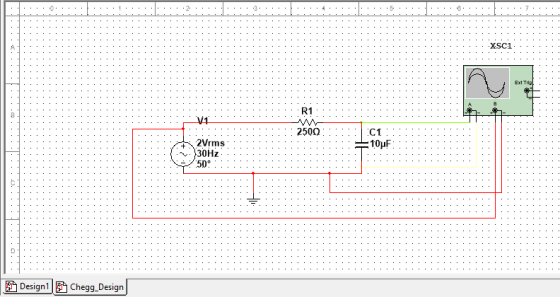
Settings for the 5.2A function generator: • AC Sine Wave • f = 30 Hz • Phase Shift = 50° • Offset = 0 V • Amplitude = 2 V

Homework Answers
MULTISIM DESIGN
OSCILLOSCOPE SPECIFICATIONS
Vrms= 2V
Frequency = 30Hz
Phase shift = 50o (as mentioned in the question)
Calculated time period =


= 33.14 ms
Simulation Results
OSCILLOSCOPE
Note -- Red color indicates input and green color indicates input.
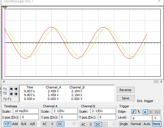
INPUT Vs OUTPUT
| S.no | Time(sec) | Vin(V) | Vout(V) |
| 1 | 9.697 | 1.018 | -.174 |
| 2 | 9.7 | 2.211 | 1.136 |
| 3 | 9.709 | 1.711 | 2.253 |
PHASE SHIFT

Clearly time difference between two maxima is


=26.466
C
OUTPUT TIME PERIOD
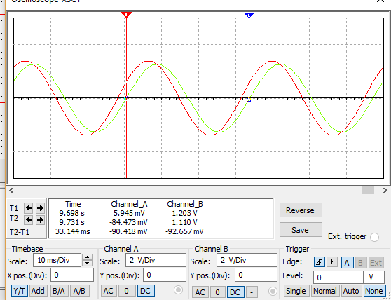
HERE OUTPUT TIME PERIOD T2-T1=33.144 mS
INPUT TIME PERIOD

HERE INPUT TIME PERIOD IS T2-T1= 33.142mS
frequency =30 Hz
Yes ouput and input time period is same And hence Frequency
Add Answer to:
Settings for the 5.2A function generator: • AC Sine Wave • f = 30 Hz • Phase Shift = 50° • Offset...
1. Use MultiSim program to simulate the RC circuit shown in Figures 1 using nominal resistor valu...
 1. Use MultiSim program to simulate the RC circuit shown in Figures 1 using nominal resistor value of 100Ω and 10uF capacitor. Set up the function generator for: square wave, frequency 20Hz, duty cycle 50%, offset 1V, and amplitude 1V. Use Tektronix scope to display the input source and the capacitor voltage waveforms on the same display 2. Print out your schematics and print an output showing Channels A and B 3. Use the scope cursors to measure simulated t...
NI ELVISmx Basic Settings Advanced Settings Sample Rate: 200.00iS Oane10 Settings Channel 1 Settings Source AI 1 At 0 Enabled Probe Scale Volts,01, Poston pv) 100 mV 200 mV Trigger Type Sope Level M...
 NI ELVISmx Basic Settings Advanced Settings Sample Rate: 200.00iS Oane10 Settings Channel 1 Settings Source AI 1 At 0 Enabled Probe Scale Volts,01, Poston pv) 100 mV 200 mV Trigger Type Sope Level M Horizontal positon (%) 50 200 us T: 250.00 umeout Ci: 489.99 C284.13 mV CHO Meas RMS:345.95 mV Freq: 999.998 Hz Vpp: 979.42 m CH1 Meas: RMS: 59.46 mV Freq: 999.928 Hz pp: 168.31 m Instrument Control Acquiation Mode Print Log Help Autoscale Cursors OnCi CHO Fig....
Obiective To investigate and do analysis on what happens before, during and after resonance in a...
 Obiective To investigate and do analysis on what happens before, during and after resonance in a series circuit Apparatus 1 Electricity and Electronic Bread Board EEC 470 2 Function generator 3. Two channel oscilloscope Leads 4. Two Power Supply Lead 5 National Instruments Software (MultiSim Ver 13/labview) Circuit Diagram 330 95mH Figure 1 1. Preparation (16 marks]: 1.1 From figure 1. calculate in complex form the total impedance Z total at a frequency of 250 Hz, (4) 11.1 Draw waveforms...
3 Circuit C2 R1 Connect to Vo Unity Gair 470 0.1uF Follower Ground Output C1 4700 R2 R3 1000 C3 luF Figure 1. AC Test C...
 3 Circuit C2 R1 Connect to Vo Unity Gair 470 0.1uF Follower Ground Output C1 4700 R2 R3 1000 C3 luF Figure 1. AC Test Circuit. 5 LTspice Simulation » Use LTspice to simulate the circuit shown in Figure 1. . The AC voltage source should have an amplitude of 5V and a frequency of 60Hz. When you enter the parameters in LTspice, you should see them displayed on the schematic as follows SINE(0 5 60000 1000) * Graph the...
Inverting Amplifier Figure 4.2 shows the fundamental configuration of Op-Amp in which it is used as...
 Inverting Amplifier Figure 4.2 shows the fundamental configuration of Op-Amp in which it is used as an inverting amplifier. In this configuration the ratio, R2/R1 completely controls the effective gain of the amplifier and it can be verified that the output voltage is equal to Vo = - (R2/R1)Vin R2 100K Q-10V R1 Vinow 20K 1 2 7 V Vo 3 -10v Figure 4.2 Part 1 - Inverting Amp: Procedure 1. Construct the circuit of figure 4.2 using Op-Amp IC...
B oth 100 Day PH262 Page 1 of 5 Lab #13 AC Circuits, Part 1 RC...
 B oth 100 Day PH262 Page 1 of 5 Lab #13 AC Circuits, Part 1 RC & RL, Phase Measurements THEORY The rotating phase representation for series AC circuits should be familiar from textbook and lecture notes A brief outline of the essential points is provided here. If a series RLC circuit is connected across a source of om which is a sinusoidal function of time, then und all its derivatives will also be inside. Sonce all demits in a...
Current Clamp Properties XFG2 NUN Ratio of voltage to current: 1 VA OK Cancel хса R2...
 Current Clamp Properties XFG2 NUN Ratio of voltage to current: 1 VA OK Cancel хса R2 OW- C1 Oscilloscope-XSC2 Current (A) Volts (V) Function generator-XFG2 Waveforms Sigal options Frequency: Duty cyde: Amplitude: Offset 50 ** 2.02 30.08 ms 20.075 10.01 Chama 61.623 my 1.560 V 1.499 V Channels LOSSY 09.08 my 48.733 Troger Edget DEB Timebase Channel A Scale: 10 ms.Ov S cale: 1 VW Xpos.) 14 . Yol.): O YA BA AB AC DC Figure 2. RC Circuit Channels...
Design a FULL WAVE BRIDGE RECTIFIER circuit that will: Take 120volts ac, 60 hz, sinusoidal waveform...
 Design a FULL WAVE BRIDGE RECTIFIER circuit that will:
Take 120volts ac, 60 hz, sinusoidal waveform and convert
it to a “regulated “dc value
giving 12 volts +, - 1 volt across a 2000-ohm output
load resistor with no more than 2%
ripple voltage.
You may assume:
a. An ideal power transformer as discussed in class.
b. For hand computations, you must assume a diode given by
Figure 4.8 page 185.
c. A filter capacitor sized per the textbook equation...
Design a FULL WAVE BRIDGE RECTIFIER circuit that will:
Take 120volts ac, 60 hz, sinusoidal waveform and convert
it to a “regulated “dc value
giving 12 volts +, - 1 volt across a 2000-ohm output
load resistor with no more than 2%
ripple voltage.
You may assume:
a. An ideal power transformer as discussed in class.
b. For hand computations, you must assume a diode given by
Figure 4.8 page 185.
c. A filter capacitor sized per the textbook equation...
Ctri Question 3 (20 Marks) Lab 1-Zener Circuits and Applications Theory: Zener diode is designed ...
 Ctri Question 3 (20 Marks) Lab 1-Zener Circuits and Applications Theory: Zener diode is designed to operate in reverse conduction. Zener breakdown occurs at a precisely defined voltage, allowing the diode to be used as a voltage reference or clipper. While Zener diodes are usually operated in reverse conduction, they may also be operated in cutoff and forward conduction. There are two different effects that are used in "Zener diodes". The only practical difference is that the two types have...
1. Why can the DSO only measure node voltages when the Function Generator is the power supply in ...
 1. Why can the DSO only measure node voltages when the Function Generator is the power supply in a circuit (unless it is using a current probe)? 2. Consider Figure 1. According to the calculations in the lab handout, if Z-1kΩ +/6914, then the phase difference (фи-фі) between u(t) and i (t) is 34.6". a. If this v(t) and i(t) were displayed on a DSO (v(t) being a node voltage and using a current probe for i(t) as shown in...
 1. Use MultiSim program to simulate the RC circuit shown in Figures 1 using nominal resistor value of 100Ω and 10uF capacitor. Set up the function generator for: square wave, frequency 20Hz, duty cycle 50%, offset 1V, and amplitude 1V. Use Tektronix scope to display the input source and the capacitor voltage waveforms on the same display 2. Print out your schematics and print an output showing Channels A and B 3. Use the scope cursors to measure simulated t...
 NI ELVISmx Basic Settings Advanced Settings Sample Rate: 200.00iS Oane10 Settings Channel 1 Settings Source AI 1 At 0 Enabled Probe Scale Volts,01, Poston pv) 100 mV 200 mV Trigger Type Sope Level M Horizontal positon (%) 50 200 us T: 250.00 umeout Ci: 489.99 C284.13 mV CHO Meas RMS:345.95 mV Freq: 999.998 Hz Vpp: 979.42 m CH1 Meas: RMS: 59.46 mV Freq: 999.928 Hz pp: 168.31 m Instrument Control Acquiation Mode Print Log Help Autoscale Cursors OnCi CHO Fig....
 Obiective To investigate and do analysis on what happens before, during and after resonance in a series circuit Apparatus 1 Electricity and Electronic Bread Board EEC 470 2 Function generator 3. Two channel oscilloscope Leads 4. Two Power Supply Lead 5 National Instruments Software (MultiSim Ver 13/labview) Circuit Diagram 330 95mH Figure 1 1. Preparation (16 marks]: 1.1 From figure 1. calculate in complex form the total impedance Z total at a frequency of 250 Hz, (4) 11.1 Draw waveforms...
 3 Circuit C2 R1 Connect to Vo Unity Gair 470 0.1uF Follower Ground Output C1 4700 R2 R3 1000 C3 luF Figure 1. AC Test Circuit. 5 LTspice Simulation » Use LTspice to simulate the circuit shown in Figure 1. . The AC voltage source should have an amplitude of 5V and a frequency of 60Hz. When you enter the parameters in LTspice, you should see them displayed on the schematic as follows SINE(0 5 60000 1000) * Graph the...
 Inverting Amplifier Figure 4.2 shows the fundamental configuration of Op-Amp in which it is used as an inverting amplifier. In this configuration the ratio, R2/R1 completely controls the effective gain of the amplifier and it can be verified that the output voltage is equal to Vo = - (R2/R1)Vin R2 100K Q-10V R1 Vinow 20K 1 2 7 V Vo 3 -10v Figure 4.2 Part 1 - Inverting Amp: Procedure 1. Construct the circuit of figure 4.2 using Op-Amp IC...
 B oth 100 Day PH262 Page 1 of 5 Lab #13 AC Circuits, Part 1 RC & RL, Phase Measurements THEORY The rotating phase representation for series AC circuits should be familiar from textbook and lecture notes A brief outline of the essential points is provided here. If a series RLC circuit is connected across a source of om which is a sinusoidal function of time, then und all its derivatives will also be inside. Sonce all demits in a...
 Current Clamp Properties XFG2 NUN Ratio of voltage to current: 1 VA OK Cancel хса R2 OW- C1 Oscilloscope-XSC2 Current (A) Volts (V) Function generator-XFG2 Waveforms Sigal options Frequency: Duty cyde: Amplitude: Offset 50 ** 2.02 30.08 ms 20.075 10.01 Chama 61.623 my 1.560 V 1.499 V Channels LOSSY 09.08 my 48.733 Troger Edget DEB Timebase Channel A Scale: 10 ms.Ov S cale: 1 VW Xpos.) 14 . Yol.): O YA BA AB AC DC Figure 2. RC Circuit Channels...
 Design a FULL WAVE BRIDGE RECTIFIER circuit that will:
Take 120volts ac, 60 hz, sinusoidal waveform and convert
it to a “regulated “dc value
giving 12 volts +, - 1 volt across a 2000-ohm output
load resistor with no more than 2%
ripple voltage.
You may assume:
a. An ideal power transformer as discussed in class.
b. For hand computations, you must assume a diode given by
Figure 4.8 page 185.
c. A filter capacitor sized per the textbook equation...
Design a FULL WAVE BRIDGE RECTIFIER circuit that will:
Take 120volts ac, 60 hz, sinusoidal waveform and convert
it to a “regulated “dc value
giving 12 volts +, - 1 volt across a 2000-ohm output
load resistor with no more than 2%
ripple voltage.
You may assume:
a. An ideal power transformer as discussed in class.
b. For hand computations, you must assume a diode given by
Figure 4.8 page 185.
c. A filter capacitor sized per the textbook equation...
 Ctri Question 3 (20 Marks) Lab 1-Zener Circuits and Applications Theory: Zener diode is designed to operate in reverse conduction. Zener breakdown occurs at a precisely defined voltage, allowing the diode to be used as a voltage reference or clipper. While Zener diodes are usually operated in reverse conduction, they may also be operated in cutoff and forward conduction. There are two different effects that are used in "Zener diodes". The only practical difference is that the two types have...
 1. Why can the DSO only measure node voltages when the Function Generator is the power supply in a circuit (unless it is using a current probe)? 2. Consider Figure 1. According to the calculations in the lab handout, if Z-1kΩ +/6914, then the phase difference (фи-фі) between u(t) and i (t) is 34.6". a. If this v(t) and i(t) were displayed on a DSO (v(t) being a node voltage and using a current probe for i(t) as shown in...
Most questions answered within 3 hours.
-
A coach uses a new technique to train gymnasts. Seven
gymnasts were randomly selected and their...
asked 55 minutes ago -
While rotating the tires on your car you notice a rock [mass =
0.1 Kg] stuck...
asked 2 hours ago -
Using MARS simulator, write MIPS programs according to
the following scenarios: Receive a positive integer number...
asked 4 hours ago -
An object in front of a concave mirror has a real image that is
11.5 cm...
asked 5 hours ago -
Consider the reaction, C3 H8 + O2 --> CO2 + H2O. How many
moles of O2...
asked 6 hours ago -
You and your opponent both roll a fair die. If you both roll the
same number,...
asked 7 hours ago -
In a study of the accuracy of fast food drive-through orders,
Restaurant A had 257 accurate...
asked 7 hours ago -
Identify and describe in detail the four categories of
institutions that could be included in a...
asked 7 hours ago -
In python
class Customer:
def __init__(self, customer_id, last_name, first_name, phone_number, address):
self._customer_id = int(customer_id)
self._last_name =...
asked 7 hours ago -
What is an example of a limitation in implementing a new
ERP system and how it...
asked 7 hours ago -
In a section of 9.7cm of an artery with a radius of 2.6mm there
is a...
asked 7 hours ago -
the two carboxylic acid groups of aspartic acid have different
acidities with pKa values of 2.1...
asked 7 hours ago