
Homework Answers
Add Answer to:
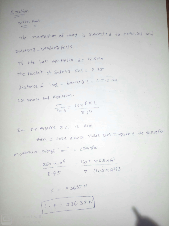
8.17A cylindrical bar of a EQ21A-T6 magnesium alloy is subjected to reversed and rotating-bending...
A cylindrical bar of ductile cast iron is subjected to reversed and rotating-bending tests, test results (i.e., S-N behavior) are shown in Animated Figure 8.21. If the bar diameter is 8.52 mm, determi...
 A cylindrical bar of ductile cast iron is subjected to reversed
and rotating-bending tests, test results (i.e., S-N
behavior) are shown in Animated Figure 8.21. If the bar diameter is
8.52 mm, determine the maximum cyclic load that may be applied to
ensure that fatigue failure will not occur. Assume a factor of
safety of 2.21 and that the distance between loadbearing points is
55.3 mm.
answer in N
We were unable to transcribe this imageReferences Cycles to failure 3.2E...
A cylindrical bar of ductile cast iron is subjected to reversed
and rotating-bending tests, test results (i.e., S-N
behavior) are shown in Animated Figure 8.21. If the bar diameter is
8.52 mm, determine the maximum cyclic load that may be applied to
ensure that fatigue failure will not occur. Assume a factor of
safety of 2.21 and that the distance between loadbearing points is
55.3 mm.
answer in N
We were unable to transcribe this imageReferences Cycles to failure 3.2E...
A cylindrical bar of ductile cast iron is subjected to reversed and rotating-bending tests, test results (i.e., S-N behavior) are shown in Animated Figure 9.27. If the bar diameter is 10.3 mm, determi...
A cylindrical bar of ductile cast iron is subjected to reversed and rotating-bending tests, test results (i.e., S-N behavior) are shown in Animated Figure 9.27. If the bar diameter is 10.3 mm, determine the maximum cyclic load that may be applied to ensure that fatigue failure will not occur. Assume a factor of safety of 2.18 and that the distance between load-bearing points is 52.4 mm.
DUC. TUJU, NUVCHULI 20, 2013 Problem 8.18 A cylindrical 4340 steel bar is subjected to reversed...
 DUC. TUJU, NUVCHULI 20, 2013 Problem 8.18 A cylindrical 4340 steel bar is subjected to reversed rotating-bending stress cycling, which yielded the test results presented in Animated Figure 8.21. If the maximum applied load is 5,000 N, compute the minimum allowable bar diameter to ensure that fatigue failure will not occur. Assume a factor of safety of 2.25 and that the distance between loadbearing points is 55.0 mm. T-SAI-2.55n titanium alloy Maximum streSMP) 1045 steel Ductile cast iron 700 30...
A cylindrical 2014-T6 aluminum alloy bar is subjected to compression-tension stress cycling along its axis, results...
 A cylindrical 2014-T6 aluminum alloy bar is subjected to compression-tension stress cycling along its axis, results of these tests are shown in Animated Figure 8.20. If the bar diameter is 10 mm, calculate the maximum allowable load amplitude (in N) to ensure that fatigue failure will not occur at 1.0 x10' cycles. Assume a factor of safety of 2.9, data in Animated Figure 8.20 were taken for reversed axial tesion-compression tests, and that S is stress amplitude. FE N [The...
A 6.4 mm diameter cylindrical rod fabricated from a 2014-T6 aluminium alloy is subjected to reversed...
 A 6.4 mm diameter cylindrical rod fabricated from a 2014-T6 aluminium alloy is subjected to reversed tension-compression load cycling along its axis of +7400 N to -2250N. Determine the fatigue life using the data shown below. 500 400 1045 steel 300 2014-T6 aluminum alloy 200 100 Red brass 10 103 104 106 105 108 10° 1010 Cycles to failure, N Stress amplitude, S (MPa)
A 6.4 mm diameter cylindrical rod fabricated from a 2014-T6 aluminium alloy is subjected to reversed...
A 6.4 mm diameter cylindrical rod fabricated from a 2014-T6 aluminium alloy is subjected to reversed tension-compression load cycling along its axis of +7400 N to -2250N. Determine the fatigue life using the data shown below. 500 400 1045 steel 300 2014-T6 aluminum alloy 200 100 Red brass 10 103 104 106 105 108 10° 1010 Cycles to failure, N Stress amplitude, S (MPa)
A 6.4 mm diameter cylindrical rod fabricated from a 2014-T6 aluminium alloy is subjected to reversed...
The cold-drawn AISI 1040 steel bar shown in the figure is subjected to a completely reversed...
 The cold-drawn AISI 1040 steel bar shown in the figure is subjected to a completely reversed axial load fluctuating between 28 kN in compression to 28 kN in tension. Estimate the fatigue factor of safety based on achieving infinite life and the yielding factor of safety. If infinite life is not predicted, estimate the number of cycles to failure. 6-mm. 25 mm + 10 mm What is the factor of safety against yielding? The factor of safety against yielding is...
aluminum bar is subjected to repeated tension-compression cycling along 4. (10) A cylindrical 2014-T6 its axis (200 MPa stress) a) Will the bar fail from fatigue? b) if bar does fail, how many cyc...
 aluminum bar is subjected to repeated tension-compression cycling along 4. (10) A cylindrical 2014-T6 its axis (200 MPa stress) a) Will the bar fail from fatigue? b) if bar does fail, how many cycles to ; and c) with bar diameter of 0.01 m, what load caused failure? Show work on graph. ailure; and c) with bar diameter of 0.01 m, what load caused failure? Show wor N 10 80 500 70 60 400 50 1045 stee lo 300 140...
The AB tube made of a magnesium alloy AM1004-T61 is covered with a rigid plate E. The spacing between E and the C-end of the CD solid circular bar, made of a 6061-T6 aluminum alloy, is 0.2mm when It...
 The AB tube made of a magnesium alloy AM1004-T61 is covered
with a rigid plate E. The spacing between E and the C-end of the CD
solid circular bar, made of a 6061-T6 aluminum alloy, is 0.2mm when
It has a temperature of 30 Centigrade. Deteremina:
a) Are the forces to which the AM1004-T61-76 tube is subjected
if the temperature of the magnesium tube rises to 130 C?
b) What is the deformation of each bar?
c) Do any of...
The AB tube made of a magnesium alloy AM1004-T61 is covered
with a rigid plate E. The spacing between E and the C-end of the CD
solid circular bar, made of a 6061-T6 aluminum alloy, is 0.2mm when
It has a temperature of 30 Centigrade. Deteremina:
a) Are the forces to which the AM1004-T61-76 tube is subjected
if the temperature of the magnesium tube rises to 130 C?
b) What is the deformation of each bar?
c) Do any of...
The cold-drawn AISI 1040 steel bar shown in the figure is subjected to a completely reversed axial load fluctuating between 28 kN in compression to 28 kN in tension. Estimate the fatigue factor of safety based on achieving infinite life and the yielding f
 The cold-drawn AISI 1040 steel bar shown in the figure is subjected to a completely reversed axial load fluctuating between 28 kN in compression to 28 kN in tension. Estimate the fatigue factor of safety based on achieving infinite life and the yielding factor of safety. If infinite life is not predicted, estimate the number of cycles to failure.
Oestion-2 The rotating shaft shown in the figure is machined from S- 570Mpa. It is subjected...
 Oestion-2 The rotating shaft shown in the figure is machined from S- 570Mpa. It is subjected to a fluctuating load varyýing om Note all length dimensions are in mm) Find the reactions (Ri and Ra) at ure is machined from AISI 1020 CD steel with S670Mpa und varying from 0 to 7000N a) shaft (at 180mm from left). upports and maximum bending moment Miman at most critical point on and b) Find the alternating g amplitude (σ.), midrange (σ )...
 A cylindrical bar of ductile cast iron is subjected to reversed
and rotating-bending tests, test results (i.e., S-N
behavior) are shown in Animated Figure 8.21. If the bar diameter is
8.52 mm, determine the maximum cyclic load that may be applied to
ensure that fatigue failure will not occur. Assume a factor of
safety of 2.21 and that the distance between loadbearing points is
55.3 mm.
answer in N
We were unable to transcribe this imageReferences Cycles to failure 3.2E...
A cylindrical bar of ductile cast iron is subjected to reversed
and rotating-bending tests, test results (i.e., S-N
behavior) are shown in Animated Figure 8.21. If the bar diameter is
8.52 mm, determine the maximum cyclic load that may be applied to
ensure that fatigue failure will not occur. Assume a factor of
safety of 2.21 and that the distance between loadbearing points is
55.3 mm.
answer in N
We were unable to transcribe this imageReferences Cycles to failure 3.2E...
 DUC. TUJU, NUVCHULI 20, 2013 Problem 8.18 A cylindrical 4340 steel bar is subjected to reversed rotating-bending stress cycling, which yielded the test results presented in Animated Figure 8.21. If the maximum applied load is 5,000 N, compute the minimum allowable bar diameter to ensure that fatigue failure will not occur. Assume a factor of safety of 2.25 and that the distance between loadbearing points is 55.0 mm. T-SAI-2.55n titanium alloy Maximum streSMP) 1045 steel Ductile cast iron 700 30...
 A cylindrical 2014-T6 aluminum alloy bar is subjected to compression-tension stress cycling along its axis, results of these tests are shown in Animated Figure 8.20. If the bar diameter is 10 mm, calculate the maximum allowable load amplitude (in N) to ensure that fatigue failure will not occur at 1.0 x10' cycles. Assume a factor of safety of 2.9, data in Animated Figure 8.20 were taken for reversed axial tesion-compression tests, and that S is stress amplitude. FE N [The...
 A 6.4 mm diameter cylindrical rod fabricated from a 2014-T6 aluminium alloy is subjected to reversed tension-compression load cycling along its axis of +7400 N to -2250N. Determine the fatigue life using the data shown below. 500 400 1045 steel 300 2014-T6 aluminum alloy 200 100 Red brass 10 103 104 106 105 108 10° 1010 Cycles to failure, N Stress amplitude, S (MPa)
A 6.4 mm diameter cylindrical rod fabricated from a 2014-T6 aluminium alloy is subjected to reversed...
A 6.4 mm diameter cylindrical rod fabricated from a 2014-T6 aluminium alloy is subjected to reversed tension-compression load cycling along its axis of +7400 N to -2250N. Determine the fatigue life using the data shown below. 500 400 1045 steel 300 2014-T6 aluminum alloy 200 100 Red brass 10 103 104 106 105 108 10° 1010 Cycles to failure, N Stress amplitude, S (MPa)
A 6.4 mm diameter cylindrical rod fabricated from a 2014-T6 aluminium alloy is subjected to reversed...
 The cold-drawn AISI 1040 steel bar shown in the figure is subjected to a completely reversed axial load fluctuating between 28 kN in compression to 28 kN in tension. Estimate the fatigue factor of safety based on achieving infinite life and the yielding factor of safety. If infinite life is not predicted, estimate the number of cycles to failure. 6-mm. 25 mm + 10 mm What is the factor of safety against yielding? The factor of safety against yielding is...
 aluminum bar is subjected to repeated tension-compression cycling along 4. (10) A cylindrical 2014-T6 its axis (200 MPa stress) a) Will the bar fail from fatigue? b) if bar does fail, how many cycles to ; and c) with bar diameter of 0.01 m, what load caused failure? Show work on graph. ailure; and c) with bar diameter of 0.01 m, what load caused failure? Show wor N 10 80 500 70 60 400 50 1045 stee lo 300 140...
 The AB tube made of a magnesium alloy AM1004-T61 is covered
with a rigid plate E. The spacing between E and the C-end of the CD
solid circular bar, made of a 6061-T6 aluminum alloy, is 0.2mm when
It has a temperature of 30 Centigrade. Deteremina:
a) Are the forces to which the AM1004-T61-76 tube is subjected
if the temperature of the magnesium tube rises to 130 C?
b) What is the deformation of each bar?
c) Do any of...
The AB tube made of a magnesium alloy AM1004-T61 is covered
with a rigid plate E. The spacing between E and the C-end of the CD
solid circular bar, made of a 6061-T6 aluminum alloy, is 0.2mm when
It has a temperature of 30 Centigrade. Deteremina:
a) Are the forces to which the AM1004-T61-76 tube is subjected
if the temperature of the magnesium tube rises to 130 C?
b) What is the deformation of each bar?
c) Do any of...
 Oestion-2 The rotating shaft shown in the figure is machined from S- 570Mpa. It is subjected to a fluctuating load varyýing om Note all length dimensions are in mm) Find the reactions (Ri and Ra) at ure is machined from AISI 1020 CD steel with S670Mpa und varying from 0 to 7000N a) shaft (at 180mm from left). upports and maximum bending moment Miman at most critical point on and b) Find the alternating g amplitude (σ.), midrange (σ )...
Most questions answered within 3 hours.
-
Using MARS simulator, write MIPS programs according to
the following scenarios: Receive a positive integer number...
asked 1 hour ago -
An object in front of a concave mirror has a real image that is
11.5 cm...
asked 1 hour ago -
Consider the reaction, C3 H8 + O2 --> CO2 + H2O. How many
moles of O2...
asked 3 hours ago -
You and your opponent both roll a fair die. If you both roll the
same number,...
asked 3 hours ago -
In a study of the accuracy of fast food drive-through orders,
Restaurant A had 257 accurate...
asked 3 hours ago -
Identify and describe in detail the four categories of
institutions that could be included in a...
asked 3 hours ago -
In python
class Customer:
def __init__(self, customer_id, last_name, first_name, phone_number, address):
self._customer_id = int(customer_id)
self._last_name =...
asked 3 hours ago -
What is an example of a limitation in implementing a new
ERP system and how it...
asked 3 hours ago -
In a section of 9.7cm of an artery with a radius of 2.6mm there
is a...
asked 3 hours ago -
the two carboxylic acid groups of aspartic acid have different
acidities with pKa values of 2.1...
asked 3 hours ago -
Would CuCO3 aqueous salt combined with calcium chloride
form a solid precipitate? If so, what would...
asked 3 hours ago -
How do ECM Solutions assist in embedding a culture of continuous
improvement in an organization? (Project...
asked 4 hours ago