
Homework Answers

Add Answer to:
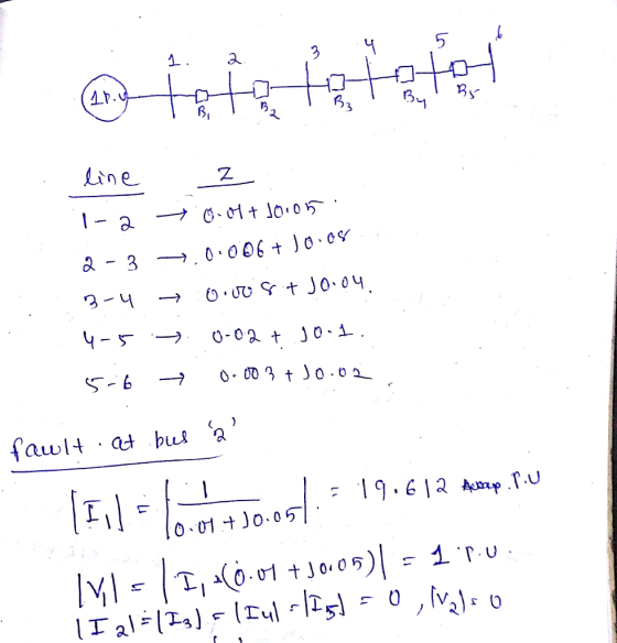
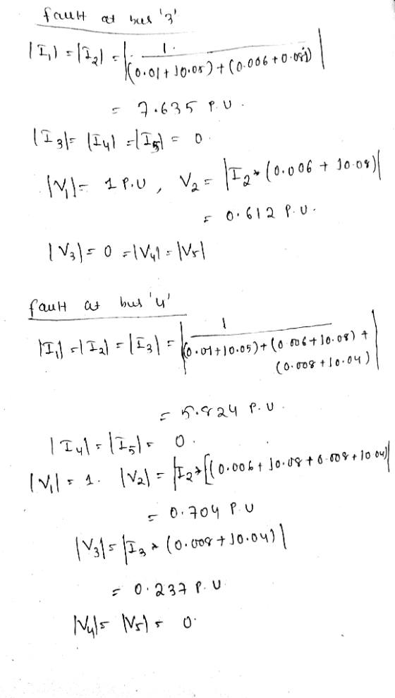
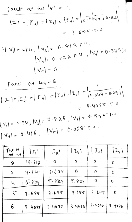
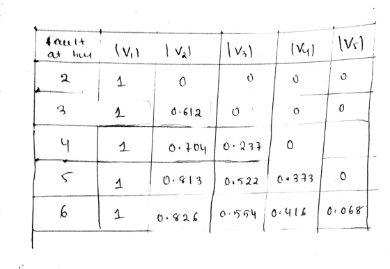
Problem5 1 pu The per-unit line impedances between buses 1-6 in the system shown above ane 1-2 0....
Busl Bus2 Bus3 Figure 1: One line diagram All impedances are specified in per unit. For...
 Busl Bus2 Bus3 Figure 1: One line diagram All impedances are specified in per unit. For generators, assume Z'- Zj0.2,Z- j0.05 For transformers, assume Z -Z -Zo - j0.05 For lines assume Z+= Z'=j0.1,20-jo.3 Assume unloaded pre-fault condition with voltages 1.0 pu at all the three buses. A fault occurs at bus 1. Ignore phase shift and perform the following computations: A. Draw the sequence network diagrams (positive, negative and zero) and find the Thevenin equivalent for each sequence network...
A 3-phase, 1000-MVA, 20-kV, 60-Hz synchronous generator is connected to an infinite bus as shown below. All impedances are given in pu values. The generator delivers 0.9 pu power at unity power factor to the infinite bus whose voltage is at 1 p
 A 3-phase, 1000-MVA, \(20-\mathrm{kV}, 60-\mathrm{Hz}\) synchronous generator is connected to an infinite bus as shown below. All impedances are given in pu values. The generator delivers \(0.9\) pu power at unity power factor to the infinite bus whose voltage is at 1 pu.If phase 'A' of circuit 2 (CCT 2) between buses H1 and H2 is suddenly opened at point ' \(\mathrm{F}\) ' near bus H1 due to the opening of a circuit breaker, determine:(a) [10 marks] The internal voltage...
The single-line diagram of a four-bus system and its bus impedance matrix are shown below BUS...
 The single-line diagram of a four-bus system and its bus impedance matrix are shown below BUS 2 0.25 j0.2 0.125 0.25 0.4 BUS 3 BUS 1 BUS 4 j0.1 0.1 j0.2 j0.2 ground is the reference node) 0.25 0.2 0.16 0.14 0.2 0.23 0.15 0.151 ZBUs =기0.16 0.15 0.196 0.1 0.14 0.151 0. 0.195 A solid three-phase fault occurs at bus 2 of the network. (a) Calculate the initial symmetrical RMS current in the fault. (b) Determine the voltages during...
Q2. (40) Eig. 1 shows the one-line diagram of a simple three-bus power system with generation at bus 1. The magnitude of voltage at bus 1 is adjusted to 1.05 pu. The scheduled loads at buses 2 and 3...
 Q2. (40) Eig. 1 shows the one-line diagram of a simple three-bus power system with generation at bus 1. The magnitude of voltage at bus 1 is adjusted to 1.05 pu. The scheduled loads at buses 2 and 3 are as marked on the diagram. Line imepdances are marked in pu on a 100 MVA base and the line charging susceptances are neglected a) (30) Using the GS (Gauss-Seidael) method, voltage phasors at the load buses 2 and 3 (P-Q...
A single line diagram of a power system is shown in Fig. 2. The system data with equipment ratings and assumed sequence reactances are given the following table. The neutrals of the generator and A-Y...
 A single line diagram of a power system is shown in Fig. 2. The system data with equipment ratings and assumed sequence reactances are given the following table. The neutrals of the generator and A-Y transformers are solidly grounded. The motor neutral is grounded through a reactance Xn 0.05 per unit on the motor base. Assume that Pre-fault voltage is takin as VF-1.0 ,0° per unit and Pre- fault load current and Δ-Y transformer phase shift are neglected In the...
The component parameters for the power system shown in Figure 2 are given in Table 1. The pre-fau...
 The component parameters for the power system shown in Figure 2 are given in Table 1. The pre-fault voltage is 120° pu and Zx-j0.1 pu. Table 1 Ratings X2-Xi (pu)Xo (pu) 0.05 0.10 0.20 0.20 Components G1, G2 200 MVA, 20 kV 0.10 0.10 0.10 0.10 T1, T2, T3200 MVA, 20/200 kV L1 200 MVA, 200 kV し2 200 MVA, 20 kV (a) Draw the three sequence networks and determine the per-unit Thevenin impedance of each sequence network seen from...
Consider the system Shown in the single-line diagram of Figure (3). All reactance are shown in per unit to the same base. Assume that the voltage at both sources is 1 p.u.
 Consider the system shown in the single-line diagram of Figure (3). All reactances are shown in per unit to the same base. Assume that the voltage at both sources is \(1 \mathrm{p}\).u.
a- Find the fault current due to a bolted- three-phase short circuit at bus \(3 .[10\) points \(]\)
b- Find the fault current supplied by each generator and the voltage at each of the buses 1 and 2 under fault conditions. \([10\) points \(]\)
Consider the system shown in the single-line diagram of Figure (3). All reactances are shown in per unit to the same base. Assume that the voltage at both sources is \(1 \mathrm{p}\).u.
a- Find the fault current due to a bolted- three-phase short circuit at bus \(3 .[10\) points \(]\)
b- Find the fault current supplied by each generator and the voltage at each of the buses 1 and 2 under fault conditions. \([10\) points \(]\)
Bus A Bus B R1 TI ine 1 20% 80% line 2 T2 R2 110 kV 11 kV The fault is located at point F, which ...
 Bus A Bus B R1 TI ine 1 20% 80% line 2 T2 R2 110 kV 11 kV The fault is located at point F, which is 20% of the total line 2 length from Bus B Fault MVA 1524.20471 Three-phase fault level in MVA at bus A SPFL (kA) 8 MVA1 MVA2 X1 (96 X2 (96) R1 (2) R2 (Q) z' (Q) Zo (2) Rf (Q) Single phase to ground fault level (kA) at bus A Transformer 1 MVA...
The six-bus system shown in Figure 1 will be simulated using MATLAB. Transmission line data and b...
 The six-bus system shown in Figure 1 will be simulated using MATLAB. Transmission line data and bus data are given in Tables 1 and 2 respectively. The transmission line data are calculated on 100 MVA base and 230 (line-to-line) kV base for generator. Tasks: 1. Determine the network admittance matrix Y 2. Find the load flow solution using Gauss-Seidel/Newton Raphson method until first iteration by manual calculation. Use Maltab software to solve power flow problem using Gauss-Seidel method. Find the...
Q2. i) The one-line diagram of simple three-bus power system with generation at bus 1 is shown in figure Q2. 0.02 + 30.04 2 256.6 MW 0.0125 + 30.025 +110.2 Mvar 0.01 + 30.03 Slack Bus 3 Vi = 1.0520° 138.6 MW 45.2 Mvar Figure Q2 The magnitude of voltage at
Q2. i) The one-line diagram of simple three-bus power system with generation at bus 1 is shown in figure Q2. 0.02 + 30.04 2 256.6 MW 0.0125 + 30.025 +110.2 Mvar 0.01 + 30.03 Slack Bus 3 Vi = 1.0520° 138.6 MW 45.2 Mvar Figure Q2 The magnitude of voltage at bus 1 is adjusted to 1.05 per unit. The scheduled loads at buses 2 and 3 are as marked on the diagram. Line impedances are marked in per unit...
 Busl Bus2 Bus3 Figure 1: One line diagram All impedances are specified in per unit. For generators, assume Z'- Zj0.2,Z- j0.05 For transformers, assume Z -Z -Zo - j0.05 For lines assume Z+= Z'=j0.1,20-jo.3 Assume unloaded pre-fault condition with voltages 1.0 pu at all the three buses. A fault occurs at bus 1. Ignore phase shift and perform the following computations: A. Draw the sequence network diagrams (positive, negative and zero) and find the Thevenin equivalent for each sequence network...
 The single-line diagram of a four-bus system and its bus impedance matrix are shown below BUS 2 0.25 j0.2 0.125 0.25 0.4 BUS 3 BUS 1 BUS 4 j0.1 0.1 j0.2 j0.2 ground is the reference node) 0.25 0.2 0.16 0.14 0.2 0.23 0.15 0.151 ZBUs =기0.16 0.15 0.196 0.1 0.14 0.151 0. 0.195 A solid three-phase fault occurs at bus 2 of the network. (a) Calculate the initial symmetrical RMS current in the fault. (b) Determine the voltages during...
 Q2. (40) Eig. 1 shows the one-line diagram of a simple three-bus power system with generation at bus 1. The magnitude of voltage at bus 1 is adjusted to 1.05 pu. The scheduled loads at buses 2 and 3 are as marked on the diagram. Line imepdances are marked in pu on a 100 MVA base and the line charging susceptances are neglected a) (30) Using the GS (Gauss-Seidael) method, voltage phasors at the load buses 2 and 3 (P-Q...
 A single line diagram of a power system is shown in Fig. 2. The system data with equipment ratings and assumed sequence reactances are given the following table. The neutrals of the generator and A-Y transformers are solidly grounded. The motor neutral is grounded through a reactance Xn 0.05 per unit on the motor base. Assume that Pre-fault voltage is takin as VF-1.0 ,0° per unit and Pre- fault load current and Δ-Y transformer phase shift are neglected In the...
 The component parameters for the power system shown in Figure 2 are given in Table 1. The pre-fault voltage is 120° pu and Zx-j0.1 pu. Table 1 Ratings X2-Xi (pu)Xo (pu) 0.05 0.10 0.20 0.20 Components G1, G2 200 MVA, 20 kV 0.10 0.10 0.10 0.10 T1, T2, T3200 MVA, 20/200 kV L1 200 MVA, 200 kV し2 200 MVA, 20 kV (a) Draw the three sequence networks and determine the per-unit Thevenin impedance of each sequence network seen from...
 Bus A Bus B R1 TI ine 1 20% 80% line 2 T2 R2 110 kV 11 kV The fault is located at point F, which is 20% of the total line 2 length from Bus B Fault MVA 1524.20471 Three-phase fault level in MVA at bus A SPFL (kA) 8 MVA1 MVA2 X1 (96 X2 (96) R1 (2) R2 (Q) z' (Q) Zo (2) Rf (Q) Single phase to ground fault level (kA) at bus A Transformer 1 MVA...
 The six-bus system shown in Figure 1 will be simulated using MATLAB. Transmission line data and bus data are given in Tables 1 and 2 respectively. The transmission line data are calculated on 100 MVA base and 230 (line-to-line) kV base for generator. Tasks: 1. Determine the network admittance matrix Y 2. Find the load flow solution using Gauss-Seidel/Newton Raphson method until first iteration by manual calculation. Use Maltab software to solve power flow problem using Gauss-Seidel method. Find the...
Most questions answered within 3 hours.
-
Write the ionic equations for the first stage of salts
hydrolysis.
Anion, Cation?
Na2S
NiSO4
K2SO4...
asked 6 minutes ago -
suppose there is a normally distributed population with a mean of
250 and a standard deviation...
asked 49 minutes ago -
Question Three
Suppose you as project manager are using the Waterfall
development methodology on a large...
asked 1 hour ago -
Which statement is not true about welfare in Canada?
A.Benefits typically vary based on one's ability...
asked 2 hours ago -
Please help me with FLOWCHART and UML diagram for class,
thank you!
#include <iostream>
#include <fstream>...
asked 3 hours ago -
3. Describe the “logic circuit” of the Lac operon. Which
proteins are bound or not to...
asked 3 hours ago -
Ayesha’s adjusted gross income is $60,000 in 2019. She donated a
piece of artwork with a...
asked 3 hours ago -
For Dijkstra’s shortest path algorithm:
a. Give the Big-O time for Dijkstra’s shortest path algorithm
and...
asked 3 hours ago -
Phosphorus violates the 'octet rule' in biological molecules,
forming more covalent bonds than expected based on...
asked 3 hours ago -
A 1.3 eV electron has a 10-4 probability of tunneling
through a 2.4 eV potential barrier....
asked 3 hours ago -
What is the one ingredient that is common to being successful
with all stakeholders?
profit
trust...
asked 3 hours ago -
Write an assembly language 32 bit program that reads in lines of
text by a .txt...
asked 3 hours ago