
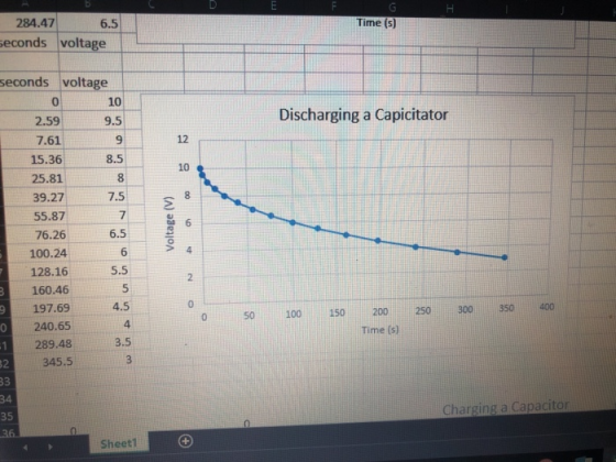

284.47 6.5 econds voltage Time (s) seconds voltage 10 9.5 9 8.5 Discharging a Capicitator 2.59 7.61 15.36 25.81 39.27 55.87 76.26 100.24 128.16 160,46 197.69 240.65 289,48 12 10 7.5 6.5 6 5.5 P 4 4.5 4 3.5 50 100 150200 250 300 350 400 Time (s) 345.5 Charging a Capacitor 35 Sheetl
.3.1 Data Analysis 1. Transfer your data for the large time constant to Excel. 2. Plot the voltag e Vo across the capacitor as a function of time for both the charging and discharging data. Include appropriate labels for the title and axes of each graph. You will have four separate graphs for this step. 3. Determining the experimental time constant. Method 1: The time constarnt T RC is the time for the capacitor to charge to within (1/e)th of its full charge for the given voltage (that is, Ve = 0.63216), or the time for the capacitor to discharge to (1/e)th of it initial value (that is, le 0.36%). Print the graphs from the last step and use each graph to approximate the time constant by identifying the point on the graph when the voltage is at the appropriate value. You may need to interpolate between data points. Clearly label the point you used on each graph. 4. Determining the experimental time constant. Method 2: Plot In(Vo) versus t for the discharging data. Is this nearly a straight line? Why? Add a linear equation of best fit to the graph and display the equation on the graph. Use the equation to ydetermine the time constant τ = RC
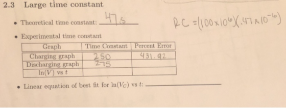
2.3 Large time constant L'e- pc:1100x10%47K(0-o) Theoretical time constant: . Experimental time constant [ Graph 1 Charging graph Discharging graph Time Constant Percent Error 31 92 1S vs t Linear equation of best fit for In(Vc) vs t
Homework Answers
Hi,
I also noticed the large discrepancy between the theoretical time constant (which you have correctly computed to be 47sec, and the experimentally observed value of around 250 second. I assume that you are looking for some explanation for this. If that be the case here are some potential sources of error:
1 Type of capacitor used. If it is a ceramic capacitors then tolerance of 20% or sometimes even higher are common. Temperature variations also affect the value of ceramic capacitors quite a bit.
2 Tolerance on resistance: This should be around 5% for carbon-film resistors typically but a bad component does occasionally creep in. In case you have the option of measuring the value of resistor with a digital multimeter, please do not touch the resistor leads when its value is being measured.
3. Sometimes a wrong value of component get used, accidently. So please cross-check, if you can, whether 0.47microfarad and 100megaohm were the ones actually used.
Now coming to the last part, i.e. Ln(Vc) versus t graph. The graph is given in the image below:
 This is nearly a straight line.
Its equation can be derived from capacitor discharging
equation:
This is nearly a straight line.
Its equation can be derived from capacitor discharging
equation:
Vc = 10*exp(-t/tc) where tc = time constant
taking ln on both side
ln(Vc) = ln(10) - t/tc
So -1/tc is the slope of the line, and ln(10) is the y-axis intercept
Therefore
ln(Vc) = 2.3-0.00373t
As expected, this graph also indicates the time constant is around 268seconds.
Hope this helps in some manner.
Add Answer to:
Resistor - 100 mega-ohms capacitor - .47 micro farads i am having an extremely hard time finding...
Construct a RC circuit (series) with a capacitor, a resistor, a battery,
 Part A Charging of RC Circuit 1) Construct a RC circuit (series) with a capacitor, a resistor, a battery, two switches, and appropriate meters that will enable you to make measurements of the parameters for charging up the capacitor. The placement of the switches allows you to measure both charging and discharging of the RC circuit. See diagram below: 2) Choose a combination of Rand C that will give you a time constant(T) of 20 seconds. T=R*C 20= 100* C=0.2F 3) Set the...
help please, i dont know how to do it Charging A 1000uF capacitor was charged using...
 help please, i dont know how to do it
Charging A 1000uF capacitor was charged using a battery of Vo = 10V via two resistors Ry = 47kN and R2 = 27k1. The simulation was run for a total time duration of 300s. Fig 1(a) shows the charging circuit used for the simulation, Fig 1() shows the Voltage vs. time (V-t) response of the circuit charging via Rę = 47kN and Fig 1(c) shows the (V-1) response of the circuit...
help please, i dont know how to do it
Charging A 1000uF capacitor was charged using a battery of Vo = 10V via two resistors Ry = 47kN and R2 = 27k1. The simulation was run for a total time duration of 300s. Fig 1(a) shows the charging circuit used for the simulation, Fig 1() shows the Voltage vs. time (V-t) response of the circuit charging via Rę = 47kN and Fig 1(c) shows the (V-1) response of the circuit...
8. Capacitance in circuits, RC circuits When a voltage source Vo is applied to a capacitor...
 8. Capacitance in circuits, RC circuits When a voltage source Vo is applied to a capacitor in a circuit which has a resistance R, a charge Q CV will build up across the capacitor. This does not happen instantaneously, but takes some time. The charge builds up exponentially with a characteristic time r = RC. Charging: V = v. 1 - e-t/RC) Discharging: Vc = V e-t/RC Page 2 of 3 When t = RC , the exponential is lle,...
، Question 2: 12 points The RC Circuit The following data were taken from the RC time constant charging a capacitor experiment. Current I(HA) Time (sec) In (Ie) 100 73.5 56.0 18.5 8.7 1.5 7.0 13.0...
 ،
Question 2: 12 points The RC Circuit The following data were taken from the RC time constant charging a capacitor experiment. Current I(HA) Time (sec) In (Ie) 100 73.5 56.0 18.5 8.7 1.5 7.0 13.0 38.0 55.0 95.0 a) Fill the table below, (2 points) b) Plot In (V Lo) versus time t in seconds. (4 points) c) Deternine the slope of the best straight line. (2 points) d) Calculate the time constant. (2 points) e) Compare the value...
،
Question 2: 12 points The RC Circuit The following data were taken from the RC time constant charging a capacitor experiment. Current I(HA) Time (sec) In (Ie) 100 73.5 56.0 18.5 8.7 1.5 7.0 13.0 38.0 55.0 95.0 a) Fill the table below, (2 points) b) Plot In (V Lo) versus time t in seconds. (4 points) c) Deternine the slope of the best straight line. (2 points) d) Calculate the time constant. (2 points) e) Compare the value...
Experiment 7 - The Resistor Capacitor Circuit Learning Objectives: Understand the short and long time behavior...
 Experiment 7 - The Resistor Capacitor Circuit Learning Objectives: Understand the short and long time behavior of circuits containing capacitors. Understand the and the mathematical relationshin between the current through the circuit as a function time, resistance, capacitance, and potential difference 1. Understanding the models for the behavior of a capacitor in a circuit A capacitor is a device that stores energy in a circuit as potential energy in an electric field. In the simple circuit drawn on the night,...
PLEASE ANSWER VERY QUICKLY!! I RATE HIGH!! The experiment is on RC circuits and the aim is to determine the time constant. Your group sets up the circuit with a resistor R and a capacitor C conne...
 PLEASE ANSWER VERY QUICKLY!! I RATE HIGH!!
The experiment is on RC circuits and the aim is to determine the time constant. Your group sets up the circuit with a resistor R and a capacitor C connected to a switch and an ideal battery (E). The circuit diagram is shown in the figure. You close the switch at time Os and the voltage across the capacitor Ve and current I in the ammeter are recorded in a spreadsheet using a...
PLEASE ANSWER VERY QUICKLY!! I RATE HIGH!!
The experiment is on RC circuits and the aim is to determine the time constant. Your group sets up the circuit with a resistor R and a capacitor C connected to a switch and an ideal battery (E). The circuit diagram is shown in the figure. You close the switch at time Os and the voltage across the capacitor Ve and current I in the ammeter are recorded in a spreadsheet using a...
tor is charged to an initial voltage of 1OV micro- discharge through a 40 kQ resistor. You take 10 is then tsof voltage versus time and record a vol 10 It is rements o and a voltage reading of.47 vol...
 tor is charged to an initial voltage of 1OV micro- discharge through a 40 kQ resistor. You take 10 is then tsof voltage versus time and record a vol 10 It is rements o and a voltage reading of.47 volts after 60 after 50 seco What is your percent of .47 volts after 60 seconds. ent error against the theoretical value of the voltage reading after three time constants? 6% -6% c.60% d. -60% What is the equation for the...
 Part A Charging of RC Circuit 1) Construct a RC circuit (series) with a capacitor, a resistor, a battery, two switches, and appropriate meters that will enable you to make measurements of the parameters for charging up the capacitor. The placement of the switches allows you to measure both charging and discharging of the RC circuit. See diagram below: 2) Choose a combination of Rand C that will give you a time constant(T) of 20 seconds. T=R*C 20= 100* C=0.2F 3) Set the...
 help please, i dont know how to do it
Charging A 1000uF capacitor was charged using a battery of Vo = 10V via two resistors Ry = 47kN and R2 = 27k1. The simulation was run for a total time duration of 300s. Fig 1(a) shows the charging circuit used for the simulation, Fig 1() shows the Voltage vs. time (V-t) response of the circuit charging via Rę = 47kN and Fig 1(c) shows the (V-1) response of the circuit...
help please, i dont know how to do it
Charging A 1000uF capacitor was charged using a battery of Vo = 10V via two resistors Ry = 47kN and R2 = 27k1. The simulation was run for a total time duration of 300s. Fig 1(a) shows the charging circuit used for the simulation, Fig 1() shows the Voltage vs. time (V-t) response of the circuit charging via Rę = 47kN and Fig 1(c) shows the (V-1) response of the circuit...
 8. Capacitance in circuits, RC circuits When a voltage source Vo is applied to a capacitor in a circuit which has a resistance R, a charge Q CV will build up across the capacitor. This does not happen instantaneously, but takes some time. The charge builds up exponentially with a characteristic time r = RC. Charging: V = v. 1 - e-t/RC) Discharging: Vc = V e-t/RC Page 2 of 3 When t = RC , the exponential is lle,...
 ،
Question 2: 12 points The RC Circuit The following data were taken from the RC time constant charging a capacitor experiment. Current I(HA) Time (sec) In (Ie) 100 73.5 56.0 18.5 8.7 1.5 7.0 13.0 38.0 55.0 95.0 a) Fill the table below, (2 points) b) Plot In (V Lo) versus time t in seconds. (4 points) c) Deternine the slope of the best straight line. (2 points) d) Calculate the time constant. (2 points) e) Compare the value...
،
Question 2: 12 points The RC Circuit The following data were taken from the RC time constant charging a capacitor experiment. Current I(HA) Time (sec) In (Ie) 100 73.5 56.0 18.5 8.7 1.5 7.0 13.0 38.0 55.0 95.0 a) Fill the table below, (2 points) b) Plot In (V Lo) versus time t in seconds. (4 points) c) Deternine the slope of the best straight line. (2 points) d) Calculate the time constant. (2 points) e) Compare the value...
 Experiment 7 - The Resistor Capacitor Circuit Learning Objectives: Understand the short and long time behavior of circuits containing capacitors. Understand the and the mathematical relationshin between the current through the circuit as a function time, resistance, capacitance, and potential difference 1. Understanding the models for the behavior of a capacitor in a circuit A capacitor is a device that stores energy in a circuit as potential energy in an electric field. In the simple circuit drawn on the night,...
 PLEASE ANSWER VERY QUICKLY!! I RATE HIGH!!
The experiment is on RC circuits and the aim is to determine the time constant. Your group sets up the circuit with a resistor R and a capacitor C connected to a switch and an ideal battery (E). The circuit diagram is shown in the figure. You close the switch at time Os and the voltage across the capacitor Ve and current I in the ammeter are recorded in a spreadsheet using a...
PLEASE ANSWER VERY QUICKLY!! I RATE HIGH!!
The experiment is on RC circuits and the aim is to determine the time constant. Your group sets up the circuit with a resistor R and a capacitor C connected to a switch and an ideal battery (E). The circuit diagram is shown in the figure. You close the switch at time Os and the voltage across the capacitor Ve and current I in the ammeter are recorded in a spreadsheet using a...
 tor is charged to an initial voltage of 1OV micro- discharge through a 40 kQ resistor. You take 10 is then tsof voltage versus time and record a vol 10 It is rements o and a voltage reading of.47 volts after 60 after 50 seco What is your percent of .47 volts after 60 seconds. ent error against the theoretical value of the voltage reading after three time constants? 6% -6% c.60% d. -60% What is the equation for the...
Most questions answered within 3 hours.
-
A crate slides up a frictionless slope. At the end of 3 seconds
its velocity is...
asked 7 minutes ago -
Use the following information to answer the next seven
questions.
Suppose there are three potential states...
asked 3 minutes ago -
If we only have interstitial and substitutional diffusion, then
what do we consider the process of...
asked 19 minutes ago -
You look at yourself in a shiny 9.6-cm-diameter Christmas tree
ball.
If your face is 21.0...
asked 21 minutes ago -
If we were to measure the relaxation time of a muscle after
undergoing tetanus compared to...
asked 20 minutes ago -
4CO(g) + 8H2(g) -----> 3CH4(g) +
CO2(g) + 2H2O(l)
Use the following data as needed to...
asked 23 minutes ago -
without using map
1. Write a C++ program to find out the top 10 words in...
asked 37 minutes ago -
1)Calculate the percent ionization of a
0.330 M solution of hypochlorous
acid.
% Ionization = %...
asked 39 minutes ago -
1a) How many grams of K2SO4 are in 250mL
of 0.11 M K2SO4 solution?
_____ g...
asked 30 minutes ago -
The vapor pressure of a solution containing 38.7 g glycerin
(C3H8O3) in 146.2 g ethanol (C2H5OH)...
asked 35 minutes ago -
A physics major is cooking breakfast when he notices that the
frictional force between the steel...
asked 41 minutes ago -
A cyclohexane (c-hex) solution is prepared by fully dissolving
9.11g of a newly synthesized organic compound...
asked 47 minutes ago