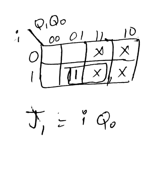
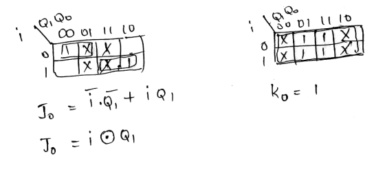
Minimize and Simplify using the Array Technique
Code using Verilog
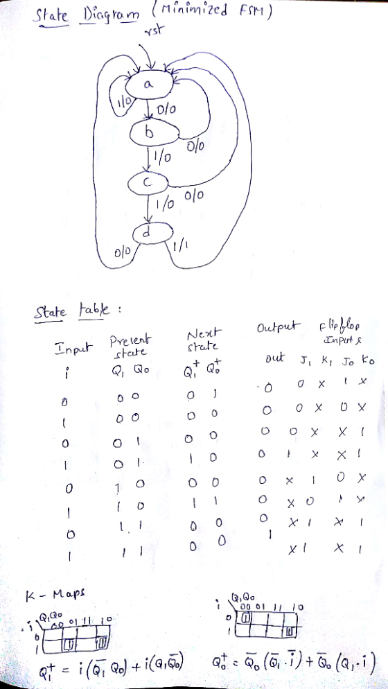
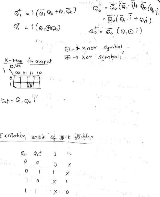
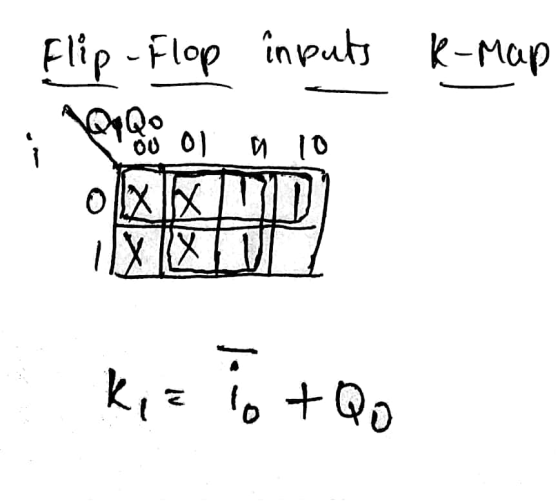
Homework Answers
//JK Flip Flop Module verilog code
module jkff(rst,clk,j,k,q,qbar);
//Portlist
input rst,clk,j,k;
output reg q;
output qbar;
//Sequential Block and output logic
always@(posedge clk) begin
if(rst)
q <= 1'b0;
else begin
case({j,k})
2'b00 : q <= q;
2'b01 : q <= 1'b0;
2'b10 : q <= 1'b1;
2'b11 : q <= ~q;
endcase
end
end
//Output for Q bar
assign qbar = ~q;
endmodule
//FSM Verilog Code
module FSM(
//Portlist
input i,
input clk,rst,
output reg out
);
//internal wires
wire j1,k1,j0,k0,q1,q0,q1_bar,q0_bar;
//Instantiation of JK Flip Flop
jkff JK_0(rst,clk,j0,k0,q0,q0_bar);
jkff JK_1(rst,clk,j1,k1,q1,q1_bar);
//Internal State Parameters
parameter a = 4'b00,
b = 4'b01,
c = 4'b10,
d = 4'b11;
//State Declaration
reg [1:0]current_state;
//Combo Block for JK inputs, next state for JK
assign j1 = (i & current_state[0]);
assign k1 = ((~i) | current_state[0]);
assign j0 = (i ~^ current_state[1]); //xnor
assign k0 = 1;
//Current State Block
always@(*) begin
case({q1,q0})
2'b00 : current_state = a;
2'b01 : current_state = b;
2'b10 : current_state = c;
2'b11 : current_state = d;
default:current_state = a;
endcase
end
//Output logic Sequential Block
always@(posedge clk) begin
if(rst)
out <= 1'b0;
else begin
case(current_state)
d : begin
if(i)
out <= 1'b1;
else
out <= 1'b0;
end
default:out <= 1'b0;
endcase
end
end
endmodule
//Test Bench for FSM
module test;
reg i, clk,rst;
wire out;
//Instantiation of FSM
FSM FSM_INST(i,clk,rst,out);
always begin
#5 clk = 1'b0;
#5 clk = ~clk;
end
initial begin
@(posedge clk) rst =1'b1;
@(posedge clk) rst =1'b0;
i = 1'b0;
@(posedge clk) i = 1'b1;
@(posedge clk) i = 1'b1;
@(posedge clk) i = 1'b1;
@(posedge clk) i = 1'b1;
@(posedge clk) i = 1'b0;
@(posedge clk) i = 1'b1;
@(posedge clk) i = 1'b0;
@(posedge clk) i = 1'b1;
@(posedge clk) i = 1'b1;
@(posedge clk) i = 1'b0;
@(posedge clk) i = 1'b1;
@(posedge clk) i = 1'b1;
@(posedge clk) i = 1'b1;
@(posedge clk) i = 1'b0;
repeat(2)
@(posedge clk); $finish;
end
endmodule
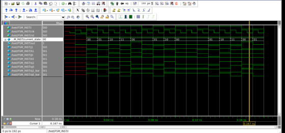
//Simulation waveform
Add Answer to:
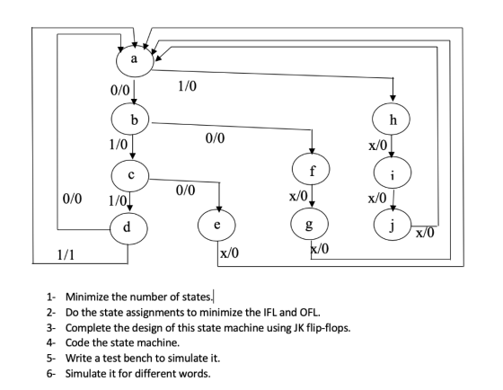
0/0 1/0 1/0 0/0 x/0 0/0 0/0 1/0 x/0 x/0 x/0 0 1 Minimize the number of states 2- Do the state ass...
1.) You have been handed a state diagram that you have been asked to implement the design for. (Unused states: extra state encodings can be treated as "don't care" values and are use...
 1.) You have been handed a state diagram that you have been asked to implement the design for. (Unused states: extra state encodings can be treated as "don't care" values and are used to simplify the combinational logic.) Next State State Name 01 State Name 020+1) 010+1) Oo+1) a. Implement the design using T flip-flops, JK flip-flops, and SR flip-flops b. Determine the Boolean expression for the inputs of the different types of flip-flops and the output.
1.) You have...
1.) You have been handed a state diagram that you have been asked to implement the design for. (Unused states: extra state encodings can be treated as "don't care" values and are used to simplify the combinational logic.) Next State State Name 01 State Name 020+1) 010+1) Oo+1) a. Implement the design using T flip-flops, JK flip-flops, and SR flip-flops b. Determine the Boolean expression for the inputs of the different types of flip-flops and the output.
1.) You have...
Design an up/down counter with four states (0, 1, 2, 3) using clocked J-K flip-flops. A...
 Design an up/down counter with four states (0, 1, 2, 3) using clocked J-K flip-flops. A control signal x is used as follows: When x 0 the machine counts forward (up), when x , backward (down). Simulate using MultiSim and attach a simulation printout X Please address the following in your report 1. State Table 2. State Diagram 3. Flip-Flop Excitation Tables 4 K-Map Simplification and resulting diagram 5. Multisim Simulation 6. Conclusion/Discussion 7. References
Design an up/down counter with...
Design an up/down counter with four states (0, 1, 2, 3) using clocked J-K flip-flops. A control signal x is used as follows: When x 0 the machine counts forward (up), when x , backward (down). Simulate using MultiSim and attach a simulation printout X Please address the following in your report 1. State Table 2. State Diagram 3. Flip-Flop Excitation Tables 4 K-Map Simplification and resulting diagram 5. Multisim Simulation 6. Conclusion/Discussion 7. References
Design an up/down counter with...
Given the State Table Below ?" ?" X-1 AB C 0 0 0O01 0OI011 01 00...
 Given the State Table Below ?" ?" X-1 AB C 0 0 0O01 0OI011 01 00 0IOI01 1 01 01OIO0 01 A. Draw a state Diagram. B. Create the "design truth table" for the "next state" and the "output" C. Make a Karnaugh for each "next state" and the "output" When making the Karnaugh maps, "xA" should be along the top and "BC" along the side (The two missing states should be considered "DONT CARES") D. Write the "Next State"...
Given the State Table Below 01* 02 03 1 203 X-1 0 000 01 0 0 0 1 0 0 A. Draw a state Diagram (5 points) B. Create the "design truth table" for the "next state" and the "output"...
 Given the State Table Below 01* 02 03 1 203 X-1 0 000 01 0 0 0 1 0 0 A. Draw a state Diagram (5 points) B. Create the "design truth table" for the "next state" and the "output" (5 points) C. Make a Karnaugh for each "next state" and the "output" (10 points) When making the Karnaugh maps, "xO1" should be along the top and "0203'" along the side (The two missing states should be considered "DONT CARES")...
Consider a finite state machine with a control input called mode. When mode = 0, the...
Consider a finite state machine with a control input called mode. When mode = 0, the machine operates as a mod-3 down counter, where the outputs are the count values. When mode = 1, the machine's output progresses through 1133 number (1 digit per clock cycle). Complete each of the steps which follow. (a) Draw the state diagram for this machine. (b) Write RTL Verilog code which implements this design. Submit your printed source code by the due date and...
Please work on Part E & F Given the State Table Below Q1 Q2 Q3 X-1 X-0 X-1 10111loloi A. Draw a state Diagram (5 points) B. Create the "design truth table" for the "next state" an...
 Please work on Part E & F
Given the State Table Below Q1 Q2 Q3 X-1 X-0 X-1 10111loloi A. Draw a state Diagram (5 points) B. Create the "design truth table" for the "next state" and the "output"' (5 points) C. Make a Karnaugh for each "next state" and the "output" (10 points) When making the Karnaugh maps, "xQ1" should be along the top and "0203" along the side (The two missing states should be considered "DONT CARES") Write...
Please work on Part E & F
Given the State Table Below Q1 Q2 Q3 X-1 X-0 X-1 10111loloi A. Draw a state Diagram (5 points) B. Create the "design truth table" for the "next state" and the "output"' (5 points) C. Make a Karnaugh for each "next state" and the "output" (10 points) When making the Karnaugh maps, "xQ1" should be along the top and "0203" along the side (The two missing states should be considered "DONT CARES") Write...
Given the State Table Below 01 02 Q3 X-1 A. B. C. Draw a state Diagram (S points) Create the "design truth table" for the "next state" and the "output" (5 points) Make...
 Given the State Table Below 01 02 Q3 X-1 A. B. C. Draw a state Diagram (S points) Create the "design truth table" for the "next state" and the "output" (5 points) Make a Karnaugh for each "next state" and the "output" (10 points) When making the Karnaugh maps, "xQ1" should be along the top and "O203" along the side (The two missing states should be considered "DONT CARES") Write the "Next State" and Output equations from the Karnaugh maps...
task 1: In digital electronics and modern computer hardware, a flip-flop is sequential digital circuit used...
 task 1: In digital electronics and modern computer hardware, a flip-flop is sequential digital circuit used as a basic memory element. It has two stable states and can be used to store state information. One of its states represents '1' while the other represents '0'. The most common types of flip-flops are SR-flip-flop, JK-flip-flop, and D flip-flop. When used in a finite-state machine, the output and next state depend not only on its current input, but also on its current...
verilog code needed for the counter using the JK flip flop please include the testbench, thanks!...
 verilog code needed for the counter using the JK flip
flop
please include the testbench, thanks!
Successfully completing a System Verilog +80Pts. Implementation showing the full sequence of ABC readouts Pre-Laboratory Exercise: You are to design a counter that will count through a sequence either forward or reverse. You will have two control inputs: Direction, and Reset'. Sequence #2: 000 100 110 111 101001 → 011 010 → 000... {Gray code} When Direction=0 follow the order listed above. When Direction...
verilog code needed for the counter using the JK flip
flop
please include the testbench, thanks!
Successfully completing a System Verilog +80Pts. Implementation showing the full sequence of ABC readouts Pre-Laboratory Exercise: You are to design a counter that will count through a sequence either forward or reverse. You will have two control inputs: Direction, and Reset'. Sequence #2: 000 100 110 111 101001 → 011 010 → 000... {Gray code} When Direction=0 follow the order listed above. When Direction...
Design a counter circuit with sequence 0, 1, 2, …, 11 and repeat using JK flip-flops....
Design a counter circuit with sequence 0, 1, 2, …, 11 and repeat using JK flip-flops. Design the circuit with pen and paper and then simulate it using Logisim (justify the input values chosen)
 1.) You have been handed a state diagram that you have been asked to implement the design for. (Unused states: extra state encodings can be treated as "don't care" values and are used to simplify the combinational logic.) Next State State Name 01 State Name 020+1) 010+1) Oo+1) a. Implement the design using T flip-flops, JK flip-flops, and SR flip-flops b. Determine the Boolean expression for the inputs of the different types of flip-flops and the output.
1.) You have...
1.) You have been handed a state diagram that you have been asked to implement the design for. (Unused states: extra state encodings can be treated as "don't care" values and are used to simplify the combinational logic.) Next State State Name 01 State Name 020+1) 010+1) Oo+1) a. Implement the design using T flip-flops, JK flip-flops, and SR flip-flops b. Determine the Boolean expression for the inputs of the different types of flip-flops and the output.
1.) You have...
 Design an up/down counter with four states (0, 1, 2, 3) using clocked J-K flip-flops. A control signal x is used as follows: When x 0 the machine counts forward (up), when x , backward (down). Simulate using MultiSim and attach a simulation printout X Please address the following in your report 1. State Table 2. State Diagram 3. Flip-Flop Excitation Tables 4 K-Map Simplification and resulting diagram 5. Multisim Simulation 6. Conclusion/Discussion 7. References
Design an up/down counter with...
Design an up/down counter with four states (0, 1, 2, 3) using clocked J-K flip-flops. A control signal x is used as follows: When x 0 the machine counts forward (up), when x , backward (down). Simulate using MultiSim and attach a simulation printout X Please address the following in your report 1. State Table 2. State Diagram 3. Flip-Flop Excitation Tables 4 K-Map Simplification and resulting diagram 5. Multisim Simulation 6. Conclusion/Discussion 7. References
Design an up/down counter with...
 Given the State Table Below ?" ?" X-1 AB C 0 0 0O01 0OI011 01 00 0IOI01 1 01 01OIO0 01 A. Draw a state Diagram. B. Create the "design truth table" for the "next state" and the "output" C. Make a Karnaugh for each "next state" and the "output" When making the Karnaugh maps, "xA" should be along the top and "BC" along the side (The two missing states should be considered "DONT CARES") D. Write the "Next State"...
 Given the State Table Below 01* 02 03 1 203 X-1 0 000 01 0 0 0 1 0 0 A. Draw a state Diagram (5 points) B. Create the "design truth table" for the "next state" and the "output" (5 points) C. Make a Karnaugh for each "next state" and the "output" (10 points) When making the Karnaugh maps, "xO1" should be along the top and "0203'" along the side (The two missing states should be considered "DONT CARES")...
 Please work on Part E & F
Given the State Table Below Q1 Q2 Q3 X-1 X-0 X-1 10111loloi A. Draw a state Diagram (5 points) B. Create the "design truth table" for the "next state" and the "output"' (5 points) C. Make a Karnaugh for each "next state" and the "output" (10 points) When making the Karnaugh maps, "xQ1" should be along the top and "0203" along the side (The two missing states should be considered "DONT CARES") Write...
Please work on Part E & F
Given the State Table Below Q1 Q2 Q3 X-1 X-0 X-1 10111loloi A. Draw a state Diagram (5 points) B. Create the "design truth table" for the "next state" and the "output"' (5 points) C. Make a Karnaugh for each "next state" and the "output" (10 points) When making the Karnaugh maps, "xQ1" should be along the top and "0203" along the side (The two missing states should be considered "DONT CARES") Write...
 Given the State Table Below 01 02 Q3 X-1 A. B. C. Draw a state Diagram (S points) Create the "design truth table" for the "next state" and the "output" (5 points) Make a Karnaugh for each "next state" and the "output" (10 points) When making the Karnaugh maps, "xQ1" should be along the top and "O203" along the side (The two missing states should be considered "DONT CARES") Write the "Next State" and Output equations from the Karnaugh maps...
 task 1: In digital electronics and modern computer hardware, a flip-flop is sequential digital circuit used as a basic memory element. It has two stable states and can be used to store state information. One of its states represents '1' while the other represents '0'. The most common types of flip-flops are SR-flip-flop, JK-flip-flop, and D flip-flop. When used in a finite-state machine, the output and next state depend not only on its current input, but also on its current...
 verilog code needed for the counter using the JK flip
flop
please include the testbench, thanks!
Successfully completing a System Verilog +80Pts. Implementation showing the full sequence of ABC readouts Pre-Laboratory Exercise: You are to design a counter that will count through a sequence either forward or reverse. You will have two control inputs: Direction, and Reset'. Sequence #2: 000 100 110 111 101001 → 011 010 → 000... {Gray code} When Direction=0 follow the order listed above. When Direction...
verilog code needed for the counter using the JK flip
flop
please include the testbench, thanks!
Successfully completing a System Verilog +80Pts. Implementation showing the full sequence of ABC readouts Pre-Laboratory Exercise: You are to design a counter that will count through a sequence either forward or reverse. You will have two control inputs: Direction, and Reset'. Sequence #2: 000 100 110 111 101001 → 011 010 → 000... {Gray code} When Direction=0 follow the order listed above. When Direction...
Most questions answered within 3 hours.
-
Do not neglect the old for the new. The existing business must
not lose priority simply...
asked 47 minutes ago -
Kylie is a single mom with two dependent children,
Tanner, age 7 and Olivia, age 11....
asked 2 hours ago -
Phosphorous + bromine = phosphorous tribromide. If 35.0 g of
bromine are reacted and 27.9 grams...
asked 3 hours ago -
Derive the long wavelength limit of the Planck energy density
distribution
asked 3 hours ago -
Calculate the pH of each of the following solutions.
0.50 M HBr
3.1×10⁻⁴ M KOH
4.2×10⁻⁵...
asked 7 hours ago -
For the year ended December 31, Depot Max’s cost of merchandise
sold was $85,600. Inventory at the...
asked 7 hours ago -
Week 10 - Professional Memo Assignment
Professional Memo Assignment
Your mission for this week, should you...
asked 7 hours ago -
Write a Python program that stores the data for each
player on the team, and it...
asked 7 hours ago -
In
the last 3 months, mike never knows when he is going to get his
allowance...
asked 7 hours ago -
Is Ca(OH)2 a Bronsted base, Lewis base, or both? Why?
asked 7 hours ago -
1A- Why don’t voters complain about U.S. tariffs on imported
sugar?
Because sugar is only a...
asked 7 hours ago -
Cash Payback Period
Primera Banco is evaluating two capital investment proposals for
a drive-up ATM kiosk,...
asked 7 hours ago