For both circuits, calculate the optimum value of Rp to minimize the offset voltage at Vo. Vin is a sine wave with a frequency of 1kHz.


R仁20K R1-2K Vin TLO74 -> Vo Rp
Homework Answers
Let us categorize two circuits into part (a) and part (b).
Part (a) is Non-inverting OPAMP configuration where-in input is applied to the non-inverting terminal of OPAMP.
Part (b) is Inverting OPAMP configuration where-in input is applied to the inverting terminal of OPAMP.
Thus, finding offset minimizing resistor "Rp" is different in
both the cases, which is shown as below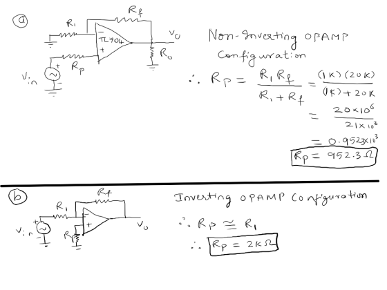
Add Answer to:
For both circuits, calculate the optimum value of Rp to minimize the offset voltage at Vo. Vin is...
Explain using theory, why does the simulation result is shown as followed Summing Amplifier
 Explain using theory, why does the simulation result is shown as
followed
Summing Amplifier
Rf Ra Rb Vo VcM Simulation condition Transient simulation (Vo vs Va,b,c) Amplitude 0.1V offsetV Frequency-1KHz Amplitude 0.05V -5V offset 5 Frequency 2KHz Amplitude 0.1V/0.2V/0.3V offset5 V Frequency 1KHz U1 R1 6 OU 20k R3 2 UA741 20k R4 R2 20k 47K V4 V5 V6 V1 cFREQ ~) VAMPL = 0 FREQ = 2k VAMPL = FREQ = 1k AC=1 GND PARAMETERS We were unable to...
Explain using theory, why does the simulation result is shown as
followed
Summing Amplifier
Rf Ra Rb Vo VcM Simulation condition Transient simulation (Vo vs Va,b,c) Amplitude 0.1V offsetV Frequency-1KHz Amplitude 0.05V -5V offset 5 Frequency 2KHz Amplitude 0.1V/0.2V/0.3V offset5 V Frequency 1KHz U1 R1 6 OU 20k R3 2 UA741 20k R4 R2 20k 47K V4 V5 V6 V1 cFREQ ~) VAMPL = 0 FREQ = 2k VAMPL = FREQ = 1k AC=1 GND PARAMETERS We were unable to...
(5pts) 11. A 0.5V peak-to-peak 1kHz sine wave with a 100mV DC offset is provided as...
 (5pts) 11. A 0.5V peak-to-peak 1kHz sine wave with a 100mV DC offset is provided as the input into a non- inverting operational amplifier with a gain of 20. If the output of the op-amp is read using an oscilloscope with AC coupling, then the value is close to a. 2V DC b. 2V peak-to-peak 1kHz sine wave c. 10V peak-to-peak 1kHz sine wave with 2V DC offset d. 10V peak-to-peak 1kHz sine wave only (5pts) 12. Which of the...
Lab ll: Voltage Follower ECE 210: 1. For the following circuit, Theoretically calculate the peak ...
 URGENT!! PLEASE HELP! be clear and answer all questions
clearly!!
Lab ll: Voltage Follower ECE 210: 1. For the following circuit, Theoretically calculate the peak voltage across R3 (Vo) an ved R1-2.2k0 2.17362(Actual) R2 = 3.3kN-3.Z44KAL (Actual) R3-10kΩ 9.873M. (Actual) Vin- 1kHz Triangle wave, 2V peak, NO DC offset e) R Draw the output waveform Vo: UI R1 R2 X-Axis 0.1 msec/div 2. Remove the resistor R2 to create the following circuit Draw the output waveform Vo: U1 R1 R3...
URGENT!! PLEASE HELP! be clear and answer all questions
clearly!!
Lab ll: Voltage Follower ECE 210: 1. For the following circuit, Theoretically calculate the peak voltage across R3 (Vo) an ved R1-2.2k0 2.17362(Actual) R2 = 3.3kN-3.Z44KAL (Actual) R3-10kΩ 9.873M. (Actual) Vin- 1kHz Triangle wave, 2V peak, NO DC offset e) R Draw the output waveform Vo: UI R1 R2 X-Axis 0.1 msec/div 2. Remove the resistor R2 to create the following circuit Draw the output waveform Vo: U1 R1 R3...
Solve parts a, b, c, and d 2. Design a differentiator circuit with an input signal that varies in frequency from 100Hz to 1KHz. Follow the differentiator guideline procedure. Select th...
 Solve parts a, b, c, and d
2. Design a differentiator circuit with an input signal that varies in frequency from 100Hz to 1KHz. Follow the differentiator guideline procedure. Select the capacitor value to be 0.1uf. Use the differentiator schematic shown on the next page. a. Draw the complete circuit showing values being used +s b. Write the expression for Vo. c. If a sine wave of 20mvp at a frequency of 1khz is applied to the input circuit. With...
Solve parts a, b, c, and d
2. Design a differentiator circuit with an input signal that varies in frequency from 100Hz to 1KHz. Follow the differentiator guideline procedure. Select the capacitor value to be 0.1uf. Use the differentiator schematic shown on the next page. a. Draw the complete circuit showing values being used +s b. Write the expression for Vo. c. If a sine wave of 20mvp at a frequency of 1khz is applied to the input circuit. With...
TODAYS CHALLENGE! For each of the following circuits, calculate the reading that the given meter(s) would...
 TODAYS CHALLENGE! For each of the following circuits, calculate the reading that the given meter(s) would display. Following that, construct the circuits paying special attention to the indicated power supply voltage and determine if theory agrees with reality. We were unable to transcribe this image
Please Help. This is a PSPICE Simulation problem. Thanks. Equipment For the laboratory experimentation, the standard...
 Please Help. This is a PSPICE Simulation problem. Thanks.
Equipment For the laboratory experimentation, the standard laboratory equipment (function generator, oscilloscope, multimeter) will be used along with a capacitor (0.027 μF), an inductor (10 mH for the series RLC circuit and 1 mH for the parallel RLC circuit), and a resistor (to be determined in your prelab work) Lab 4 PSPICE Simulation: Using the circuit parameter values given in the prelab, model the circuits given in Fig. 1 using PSPICE....
Please Help. This is a PSPICE Simulation problem. Thanks.
Equipment For the laboratory experimentation, the standard laboratory equipment (function generator, oscilloscope, multimeter) will be used along with a capacitor (0.027 μF), an inductor (10 mH for the series RLC circuit and 1 mH for the parallel RLC circuit), and a resistor (to be determined in your prelab work) Lab 4 PSPICE Simulation: Using the circuit parameter values given in the prelab, model the circuits given in Fig. 1 using PSPICE....
please show solution to 4.7 Calculate the peak value of the voltage across the inductor in...
 please show solution to 4.7
Calculate the peak value of the voltage across the inductor in figure 4.7(a), assuming Vo= 10 V, a 2t x 103 s, R= 1 2, L 25 mH, and C 1 uF. 4.6 Calculate the phase of the voltage across the inductor relative to the source in figure 4.7(a) for the values given in problem 4.6 4.7 90 Sinusoldal Circuits circuit-reducti to linear sinusoidal theorems for dc circuits can be applied cuits if the impedances...
please show solution to 4.7
Calculate the peak value of the voltage across the inductor in figure 4.7(a), assuming Vo= 10 V, a 2t x 103 s, R= 1 2, L 25 mH, and C 1 uF. 4.6 Calculate the phase of the voltage across the inductor relative to the source in figure 4.7(a) for the values given in problem 4.6 4.7 90 Sinusoldal Circuits circuit-reducti to linear sinusoidal theorems for dc circuits can be applied cuits if the impedances...
In the figure below a thin coil of radius r1= 4 cm, containing N1= 5300 turns,...
 In the figure below a thin coil of radius r1= 4 cm, containing
N1= 5300 turns, is connected through a resistor R = 100 Ω to an AC
power supply running at a frequency f= 2100 so that the current
through the resistor (and coil) is I1sin(2π×2100t). The voltage
across the resistor triggers an oscilloscope that also displays
this voltage, which is 10 V peak-to-peak and therefore has an
amplitude of 5 V (and therefore the amplitude of the current...
In the figure below a thin coil of radius r1= 4 cm, containing
N1= 5300 turns, is connected through a resistor R = 100 Ω to an AC
power supply running at a frequency f= 2100 so that the current
through the resistor (and coil) is I1sin(2π×2100t). The voltage
across the resistor triggers an oscilloscope that also displays
this voltage, which is 10 V peak-to-peak and therefore has an
amplitude of 5 V (and therefore the amplitude of the current...
Quiz-1 Review Questions: AC Circuits CETT-1405 1: Calculate the frequency “F” for each of the following...
Quiz-1 Review Questions: AC Circuits CETT-1405 1: Calculate the frequency “F” for each of the following values of sine wave period. T = 0.1 sec, F = T = 4 milli seconds, F = 2: A sine wave has a peak of 120V. Determine the Vrms value: 3: A hair dryer having 8 Ohms resistance was connected to 110 Vrms supply. Calculate the following: Irms = Ipeak = Voltage across the resistor = Power Lost as heat at...
need to get same answer The applied voltage to a series resonant circuit like that shown...
 need to get same answer
The applied voltage to a series resonant circuit like that shown in Fig. 2.2a is I V. (a) Determine how much larger the voltages across L, C, and R are at resonance Use the values R 0. I Ω, L = 0.1 mH, and C = 0.01 μ F, and first calculate the resonance frequency. (b) Should VL and Vc be larger than 1 V, explain how this is possible. Ans: (a) VL = jl...
need to get same answer
The applied voltage to a series resonant circuit like that shown in Fig. 2.2a is I V. (a) Determine how much larger the voltages across L, C, and R are at resonance Use the values R 0. I Ω, L = 0.1 mH, and C = 0.01 μ F, and first calculate the resonance frequency. (b) Should VL and Vc be larger than 1 V, explain how this is possible. Ans: (a) VL = jl...
 Explain using theory, why does the simulation result is shown as
followed
Summing Amplifier
Rf Ra Rb Vo VcM Simulation condition Transient simulation (Vo vs Va,b,c) Amplitude 0.1V offsetV Frequency-1KHz Amplitude 0.05V -5V offset 5 Frequency 2KHz Amplitude 0.1V/0.2V/0.3V offset5 V Frequency 1KHz U1 R1 6 OU 20k R3 2 UA741 20k R4 R2 20k 47K V4 V5 V6 V1 cFREQ ~) VAMPL = 0 FREQ = 2k VAMPL = FREQ = 1k AC=1 GND PARAMETERS We were unable to...
Explain using theory, why does the simulation result is shown as
followed
Summing Amplifier
Rf Ra Rb Vo VcM Simulation condition Transient simulation (Vo vs Va,b,c) Amplitude 0.1V offsetV Frequency-1KHz Amplitude 0.05V -5V offset 5 Frequency 2KHz Amplitude 0.1V/0.2V/0.3V offset5 V Frequency 1KHz U1 R1 6 OU 20k R3 2 UA741 20k R4 R2 20k 47K V4 V5 V6 V1 cFREQ ~) VAMPL = 0 FREQ = 2k VAMPL = FREQ = 1k AC=1 GND PARAMETERS We were unable to...
 (5pts) 11. A 0.5V peak-to-peak 1kHz sine wave with a 100mV DC offset is provided as the input into a non- inverting operational amplifier with a gain of 20. If the output of the op-amp is read using an oscilloscope with AC coupling, then the value is close to a. 2V DC b. 2V peak-to-peak 1kHz sine wave c. 10V peak-to-peak 1kHz sine wave with 2V DC offset d. 10V peak-to-peak 1kHz sine wave only (5pts) 12. Which of the...
 URGENT!! PLEASE HELP! be clear and answer all questions
clearly!!
Lab ll: Voltage Follower ECE 210: 1. For the following circuit, Theoretically calculate the peak voltage across R3 (Vo) an ved R1-2.2k0 2.17362(Actual) R2 = 3.3kN-3.Z44KAL (Actual) R3-10kΩ 9.873M. (Actual) Vin- 1kHz Triangle wave, 2V peak, NO DC offset e) R Draw the output waveform Vo: UI R1 R2 X-Axis 0.1 msec/div 2. Remove the resistor R2 to create the following circuit Draw the output waveform Vo: U1 R1 R3...
URGENT!! PLEASE HELP! be clear and answer all questions
clearly!!
Lab ll: Voltage Follower ECE 210: 1. For the following circuit, Theoretically calculate the peak voltage across R3 (Vo) an ved R1-2.2k0 2.17362(Actual) R2 = 3.3kN-3.Z44KAL (Actual) R3-10kΩ 9.873M. (Actual) Vin- 1kHz Triangle wave, 2V peak, NO DC offset e) R Draw the output waveform Vo: UI R1 R2 X-Axis 0.1 msec/div 2. Remove the resistor R2 to create the following circuit Draw the output waveform Vo: U1 R1 R3...
 Solve parts a, b, c, and d
2. Design a differentiator circuit with an input signal that varies in frequency from 100Hz to 1KHz. Follow the differentiator guideline procedure. Select the capacitor value to be 0.1uf. Use the differentiator schematic shown on the next page. a. Draw the complete circuit showing values being used +s b. Write the expression for Vo. c. If a sine wave of 20mvp at a frequency of 1khz is applied to the input circuit. With...
Solve parts a, b, c, and d
2. Design a differentiator circuit with an input signal that varies in frequency from 100Hz to 1KHz. Follow the differentiator guideline procedure. Select the capacitor value to be 0.1uf. Use the differentiator schematic shown on the next page. a. Draw the complete circuit showing values being used +s b. Write the expression for Vo. c. If a sine wave of 20mvp at a frequency of 1khz is applied to the input circuit. With...
 TODAYS CHALLENGE! For each of the following circuits, calculate the reading that the given meter(s) would display. Following that, construct the circuits paying special attention to the indicated power supply voltage and determine if theory agrees with reality. We were unable to transcribe this image
 Please Help. This is a PSPICE Simulation problem. Thanks.
Equipment For the laboratory experimentation, the standard laboratory equipment (function generator, oscilloscope, multimeter) will be used along with a capacitor (0.027 μF), an inductor (10 mH for the series RLC circuit and 1 mH for the parallel RLC circuit), and a resistor (to be determined in your prelab work) Lab 4 PSPICE Simulation: Using the circuit parameter values given in the prelab, model the circuits given in Fig. 1 using PSPICE....
Please Help. This is a PSPICE Simulation problem. Thanks.
Equipment For the laboratory experimentation, the standard laboratory equipment (function generator, oscilloscope, multimeter) will be used along with a capacitor (0.027 μF), an inductor (10 mH for the series RLC circuit and 1 mH for the parallel RLC circuit), and a resistor (to be determined in your prelab work) Lab 4 PSPICE Simulation: Using the circuit parameter values given in the prelab, model the circuits given in Fig. 1 using PSPICE....
 please show solution to 4.7
Calculate the peak value of the voltage across the inductor in figure 4.7(a), assuming Vo= 10 V, a 2t x 103 s, R= 1 2, L 25 mH, and C 1 uF. 4.6 Calculate the phase of the voltage across the inductor relative to the source in figure 4.7(a) for the values given in problem 4.6 4.7 90 Sinusoldal Circuits circuit-reducti to linear sinusoidal theorems for dc circuits can be applied cuits if the impedances...
please show solution to 4.7
Calculate the peak value of the voltage across the inductor in figure 4.7(a), assuming Vo= 10 V, a 2t x 103 s, R= 1 2, L 25 mH, and C 1 uF. 4.6 Calculate the phase of the voltage across the inductor relative to the source in figure 4.7(a) for the values given in problem 4.6 4.7 90 Sinusoldal Circuits circuit-reducti to linear sinusoidal theorems for dc circuits can be applied cuits if the impedances...
 need to get same answer
The applied voltage to a series resonant circuit like that shown in Fig. 2.2a is I V. (a) Determine how much larger the voltages across L, C, and R are at resonance Use the values R 0. I Ω, L = 0.1 mH, and C = 0.01 μ F, and first calculate the resonance frequency. (b) Should VL and Vc be larger than 1 V, explain how this is possible. Ans: (a) VL = jl...
need to get same answer
The applied voltage to a series resonant circuit like that shown in Fig. 2.2a is I V. (a) Determine how much larger the voltages across L, C, and R are at resonance Use the values R 0. I Ω, L = 0.1 mH, and C = 0.01 μ F, and first calculate the resonance frequency. (b) Should VL and Vc be larger than 1 V, explain how this is possible. Ans: (a) VL = jl...
Most questions answered within 3 hours.
-
The Problem: The Case of the Harmonizing Vacations
Your CEO is exploring partnering with a European...
asked 1 minute ago -
A chemical equation is balanced by adding coefficients in front
of some formulas so that the...
asked 20 seconds ago -
From the literature (reference your sources): What are the
lattice parameters of calcite and aragonite? Why...
asked 40 minutes ago -
Your system is rejecting the question am asking which is
preceded by a case study. It...
asked 44 minutes ago -
3. On January 2, 2000, Larry creates a trust with himself as
trustee. Larry as trustee...
asked 41 minutes ago -
A member of the volleyball team spikes the ball. During this
process, she changes the velocity...
asked 48 minutes ago -
Are adult gamers less likely to use a gaming console (Xbox,
PlayStation, Wii, etc...) than teen...
asked 1 hour ago -
The University of
Texas recently reported that 43% of college students aged 18-24
would spend their...
asked 1 hour ago -
The length of stay at a specific emergency department in
Phoenix, Arizona, in 2009 had a...
asked 1 hour ago -
. Please give the mechanism for this type of problem. Step by
Step
The toxin that...
asked 1 hour ago -
If you have a 1M stock solution and you want to dilute 1 :10
with water,...
asked 1 hour ago -
In a load instruction, the effective address is obtained by
A) Retriving the address from a...
asked 1 hour ago