


Solve parts a, b, c, and d
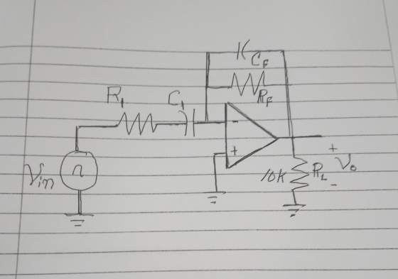
a. Draw the complete circuit showing values being used +s b. Write the expression for Vo. c. If a sine wave of 20mvp at a frequency of 1khz is applied to the input circuit. With such an input determine the output signal.
d. Sketch both the input and the output signals
Homework Answers


Add Answer to:
Solve parts a, b, c, and d 2. Design a differentiator circuit with an input signal that varies in frequency from 100Hz to 1KHz. Follow the differentiator guideline procedure. Select th...
ONLY NEED HELP WITH C AND D PLEASE! The differentiator circuit shown in Figure 1 uses an op-amp with ideal characteristics C1 Figure 1 (a) Prove that the gain of the circuit is given by the following...
 ONLY NEED HELP WITH C AND D PLEASE!
The differentiator circuit shown in Figure 1 uses an op-amp with ideal characteristics C1 Figure 1 (a) Prove that the gain of the circuit is given by the following expression using first principles for an ideal op-amp (2 marks) Gain = - (1 + juli R 1) (b) If the differentiator frequency (at unity gain) is 100Hz and the high frequency gain is 40dB and R2 is 220kQ, design the rest of...
ONLY NEED HELP WITH C AND D PLEASE!
The differentiator circuit shown in Figure 1 uses an op-amp with ideal characteristics C1 Figure 1 (a) Prove that the gain of the circuit is given by the following expression using first principles for an ideal op-amp (2 marks) Gain = - (1 + juli R 1) (b) If the differentiator frequency (at unity gain) is 100Hz and the high frequency gain is 40dB and R2 is 220kQ, design the rest of...
Op Amp Integrators and Differentiators 1.) Design an op-amp circuit that acts as an integrator. Chose...
 Op Amp Integrators and Differentiators 1.) Design an op-amp circuit that acts as an integrator. Chose R and C values to give you a gain of 5 at f-1kHz Draw out the circuit and show the input and output, label all the pin numbers and show where the +-12 power supply connections for the chip are. Turn in the circuit diagram, carefully labelled 2.) Build your circuit and measure the gain as a function of frequency. Collect enough data to...
Design a noninverting op amp circuit that will map an input signal that varies from -2...
Design a noninverting op amp circuit that will map an input signal that varies from -2 V to 2 V to an output signal that varies from -16 V to 16 V. Specify all values in the circuit.
Part I: Black Box A Design your first black box adhering to the following specifications A. Input Signal to Black Box A 1. A 1 kHz cosine wave with amplitude of 1V. B. Output Signal from Black Box A...
 Part I: Black Box A Design your first black box adhering to the following specifications A. Input Signal to Black Box A 1. A 1 kHz cosine wave with amplitude of 1V. B. Output Signal from Black Box A 1. A 1 kHz sine wave with amplitude of Hint: Use an ideal op-amp C. Explain your design process. What type of circuit did you design? Discuss D. Why did vou use an op-amp? Could another component be used instead? Why...
need help with C and D please The differentiator circuit shown in Figure 1 uses an op-amp with ideal characteristics. R2 R1 C1 Vi O Figure 1 (c) Sketch the Bode magnitude response for this circ...
 need help with C and D please
The differentiator circuit shown in Figure 1 uses an op-amp with ideal characteristics. R2 R1 C1 Vi O Figure 1 (c) Sketch the Bode magnitude response for this circuit for the frequency range of 10° to 108 Hz. (7 marks) (d) Sketch the output waveform of the differentiator and justify your answer, if v is as shown in Figure 2 with a period of: () 100 ms (ii) 10 us (6 marks) 0.11...
need help with C and D please
The differentiator circuit shown in Figure 1 uses an op-amp with ideal characteristics. R2 R1 C1 Vi O Figure 1 (c) Sketch the Bode magnitude response for this circuit for the frequency range of 10° to 108 Hz. (7 marks) (d) Sketch the output waveform of the differentiator and justify your answer, if v is as shown in Figure 2 with a period of: () 100 ms (ii) 10 us (6 marks) 0.11...
please answer question 4 (all parts of question4 please) will rate! 3. (30 pts) Design a 2-bit Gray code generator that ropetitively delivers the sequence 00301911-10-00when the input signal UP-...
 please answer question 4 (all parts of question4 please) will
rate!
3. (30 pts) Design a 2-bit Gray code generator that ropetitively delivers the sequence 00301911-10-00when the input signal UP- 1,or in reverse order 009 10기け01 →00→ when UP-0. Your design should include an asynchronous low. active reset operation: the FSM goes to 00 state when a reset signal is applied In addition to the state output z[1). 2[0]. there is a carry/borrow output bit e which is I when...
please answer question 4 (all parts of question4 please) will
rate!
3. (30 pts) Design a 2-bit Gray code generator that ropetitively delivers the sequence 00301911-10-00when the input signal UP- 1,or in reverse order 009 10기け01 →00→ when UP-0. Your design should include an asynchronous low. active reset operation: the FSM goes to 00 state when a reset signal is applied In addition to the state output z[1). 2[0]. there is a carry/borrow output bit e which is I when...
I am currently trying to figure out the experiment below. Please complete Table 1 with an...
 I am currently trying to figure out the experiment below. Please
complete Table 1 with an explanation, I appreciate it thank
you! Promise to give thumbs up!
Introduction The phase differences between the output voltage, the voltage across the inductor, the voltage across the capacitor, and the voltage across the resistor will be examined at resonant frequency. The voltage and phase relationship will also be examined for frequencies above and below resonance. Theory An inductor, a capacitor, and a resistor are...
I am currently trying to figure out the experiment below. Please
complete Table 1 with an explanation, I appreciate it thank
you! Promise to give thumbs up!
Introduction The phase differences between the output voltage, the voltage across the inductor, the voltage across the capacitor, and the voltage across the resistor will be examined at resonant frequency. The voltage and phase relationship will also be examined for frequencies above and below resonance. Theory An inductor, a capacitor, and a resistor are...
 ONLY NEED HELP WITH C AND D PLEASE!
The differentiator circuit shown in Figure 1 uses an op-amp with ideal characteristics C1 Figure 1 (a) Prove that the gain of the circuit is given by the following expression using first principles for an ideal op-amp (2 marks) Gain = - (1 + juli R 1) (b) If the differentiator frequency (at unity gain) is 100Hz and the high frequency gain is 40dB and R2 is 220kQ, design the rest of...
ONLY NEED HELP WITH C AND D PLEASE!
The differentiator circuit shown in Figure 1 uses an op-amp with ideal characteristics C1 Figure 1 (a) Prove that the gain of the circuit is given by the following expression using first principles for an ideal op-amp (2 marks) Gain = - (1 + juli R 1) (b) If the differentiator frequency (at unity gain) is 100Hz and the high frequency gain is 40dB and R2 is 220kQ, design the rest of...
 Op Amp Integrators and Differentiators 1.) Design an op-amp circuit that acts as an integrator. Chose R and C values to give you a gain of 5 at f-1kHz Draw out the circuit and show the input and output, label all the pin numbers and show where the +-12 power supply connections for the chip are. Turn in the circuit diagram, carefully labelled 2.) Build your circuit and measure the gain as a function of frequency. Collect enough data to...
 Part I: Black Box A Design your first black box adhering to the following specifications A. Input Signal to Black Box A 1. A 1 kHz cosine wave with amplitude of 1V. B. Output Signal from Black Box A 1. A 1 kHz sine wave with amplitude of Hint: Use an ideal op-amp C. Explain your design process. What type of circuit did you design? Discuss D. Why did vou use an op-amp? Could another component be used instead? Why...
 need help with C and D please
The differentiator circuit shown in Figure 1 uses an op-amp with ideal characteristics. R2 R1 C1 Vi O Figure 1 (c) Sketch the Bode magnitude response for this circuit for the frequency range of 10° to 108 Hz. (7 marks) (d) Sketch the output waveform of the differentiator and justify your answer, if v is as shown in Figure 2 with a period of: () 100 ms (ii) 10 us (6 marks) 0.11...
need help with C and D please
The differentiator circuit shown in Figure 1 uses an op-amp with ideal characteristics. R2 R1 C1 Vi O Figure 1 (c) Sketch the Bode magnitude response for this circuit for the frequency range of 10° to 108 Hz. (7 marks) (d) Sketch the output waveform of the differentiator and justify your answer, if v is as shown in Figure 2 with a period of: () 100 ms (ii) 10 us (6 marks) 0.11...
 please answer question 4 (all parts of question4 please) will
rate!
3. (30 pts) Design a 2-bit Gray code generator that ropetitively delivers the sequence 00301911-10-00when the input signal UP- 1,or in reverse order 009 10기け01 →00→ when UP-0. Your design should include an asynchronous low. active reset operation: the FSM goes to 00 state when a reset signal is applied In addition to the state output z[1). 2[0]. there is a carry/borrow output bit e which is I when...
please answer question 4 (all parts of question4 please) will
rate!
3. (30 pts) Design a 2-bit Gray code generator that ropetitively delivers the sequence 00301911-10-00when the input signal UP- 1,or in reverse order 009 10기け01 →00→ when UP-0. Your design should include an asynchronous low. active reset operation: the FSM goes to 00 state when a reset signal is applied In addition to the state output z[1). 2[0]. there is a carry/borrow output bit e which is I when...
 I am currently trying to figure out the experiment below. Please
complete Table 1 with an explanation, I appreciate it thank
you! Promise to give thumbs up!
Introduction The phase differences between the output voltage, the voltage across the inductor, the voltage across the capacitor, and the voltage across the resistor will be examined at resonant frequency. The voltage and phase relationship will also be examined for frequencies above and below resonance. Theory An inductor, a capacitor, and a resistor are...
I am currently trying to figure out the experiment below. Please
complete Table 1 with an explanation, I appreciate it thank
you! Promise to give thumbs up!
Introduction The phase differences between the output voltage, the voltage across the inductor, the voltage across the capacitor, and the voltage across the resistor will be examined at resonant frequency. The voltage and phase relationship will also be examined for frequencies above and below resonance. Theory An inductor, a capacitor, and a resistor are...
Most questions answered within 3 hours.
-
Considering gravitational time dilation, calculate the time that
passes in Earth’s surface while 1 hour passes...
asked 19 minutes ago -
Minitab Problem: Take the Lake Hume June rainfall data and find
use the processes outlined in...
asked 1 hour ago -
X Company is trying to decide whether to continue using old
equipment to make Product A...
asked 1 hour ago -
IN PYTHON ONLY !! Program 2: Re-work
program #5 (WeeklyHours) from the previous assignment such that...
asked 1 hour ago -
The average length of time between arrivals at a turnpike
toll-booth is 26 seconds. What is...
asked 3 hours ago -
(a) A piston at 6.1 atm contains a gas that occupies a volume of
3.5 L....
asked 4 hours ago -
Please answer true or false. Words
cannot be changed or added in to make it true...
asked 4 hours ago -
An empty test tube weighs 15.923 grams. Then,
MgCl2•6H2O is added into the test tube. After...
asked 4 hours ago -
Assume memory access is 10 units of time and disk access is
10000 units of time....
asked 5 hours ago -
1. Are all good samples random?
2. Magazines often report surveys giving statistics such as “63%...
asked 5 hours ago -
Under all the various types of market structures, firms
must eventually earn some economic profits for...
asked 5 hours ago -
Consider the following fitness regime for a single locus trait
with two co-dominant alleles: w11 =...
asked 5 hours ago