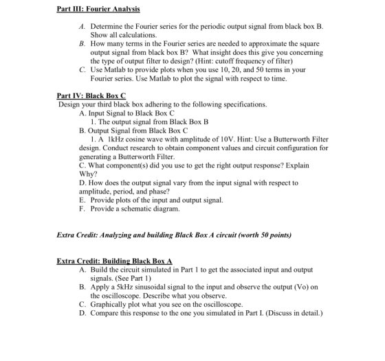
Part III: Fourier Analvsis A. Determine the Fourier series for the periodic output signal from black box B Show all calculations B. How many terms in the Fourier series are needed to approximate the square output signal from black box B? What insight does this give you concerning the type of output filter to design? (Hint: cutoff frequency of filter) C. Use Matlab to provide plots when you use 10, 20, and 50 terms in your Fourier series. Use Matlab to plot the signal with respect to time Part IV: Black Box C Design your third black box adhering to the following specifications A. Input Signal to Black Box (C 1. The output signal from Black Box B B. Output Signal from Black Box C 1. A lkHz cosine wave with amplitude of 10V. Hint: Use a Butterworth Filter design. Conduct research to obtain component values and circuit configuration for generating a Butterworth Filter. C. What component(s) did you use to get the right output response? Explain Why? D. How does the output signal vary from the input signal with respect to amplitude, period, and phase? E. Provide plots of the input and output signal F. Provide a schematic diagram Extra Credit: Analyzing and building Black Box A circuit (worth 50 points) Extra Credit: Building Black Box A. Build the circuit simulated in Part 1 to get the associated input and output signals. (See Part 1) B. Apply a 5kHz sinusoidal signal to the input and observe the output (Vo) on the oscilloscope. Describe what you observe C. Graphically plot what you see on the oscilloscope. D. Compare this response to the one you simulated in Part I. (Discuss in detail.)
Homework Answers
Add Answer to:
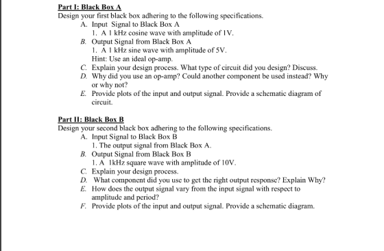
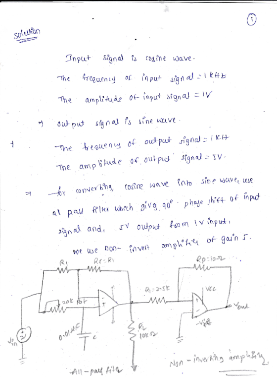
Part I: Black Box A Design your first black box adhering to the following specifications A. Input Signal to Black Box A 1. A 1 kHz cosine wave with amplitude of 1V. B. Output Signal from Black Box A...
Solve parts a, b, c, and d 2. Design a differentiator circuit with an input signal that varies in frequency from 100Hz to 1KHz. Follow the differentiator guideline procedure. Select th...
 Solve parts a, b, c, and d
2. Design a differentiator circuit with an input signal that varies in frequency from 100Hz to 1KHz. Follow the differentiator guideline procedure. Select the capacitor value to be 0.1uf. Use the differentiator schematic shown on the next page. a. Draw the complete circuit showing values being used +s b. Write the expression for Vo. c. If a sine wave of 20mvp at a frequency of 1khz is applied to the input circuit. With...
Solve parts a, b, c, and d
2. Design a differentiator circuit with an input signal that varies in frequency from 100Hz to 1KHz. Follow the differentiator guideline procedure. Select the capacitor value to be 0.1uf. Use the differentiator schematic shown on the next page. a. Draw the complete circuit showing values being used +s b. Write the expression for Vo. c. If a sine wave of 20mvp at a frequency of 1khz is applied to the input circuit. With...
1) Design a low-pass RC device with the following specifications: a) Input x(t) and output y(t)...
1) Design a low-pass RC device with the following specifications: a) Input x(t) and output y(t) b) Bandwidth which is defined as the range of frequencies (from 0 Hz to ??, the − 3dB point ) allowed to pass through without significant attenuation = 100Hz c) Static gain = 14dB d) The system has −20 dB/decade rolloff at high frequencies (thus first-order LP filter) Assume that you have one and only one resistor value available to you, and that resistance is...
2. Suppose we want to design a de power supply by filtering the output, Vree(t), of...
 2. Suppose we want to design a de power supply by filtering the output, Vree(t), of a full-wave rectifier through the following low-pass filter Choke-Input Filter Pulsating DC From Rectifier Filtered DC Output To Load Assume that the trigonometric Fourier series expansion of Vree t) is given by: Vree(t)-Vpsin(2T50t) n(1-4n2) a) From known properties of linear systems, write down an expression for the steady state output of the filter b) What are the amplitudes of the de component and the...
Part A Review The input signal to a filter contains components that range in frequency from...
 Part A Review The input signal to a filter contains components that range in frequency from 100 IIz to 50 kIIz. We wish to reduce the amplitude of the 50-kHz component by a factor of 200 by passing the signal through a first-order lowpass filter What half-power frequency is required for the filter? Express your answer to three significant figures and include the appropriate units. Correct Part B By what factor is à component at 6 kHx changed in amplitude...
for the same black box circuit how do we measure the output voltage to calculate the gain because the input voltage is 1...
 for
the same black box circuit how do we measure the output voltage to
calculate the gain because the input voltage is 12V and which
values should we set for the frequency is it Hz or kHz
this is the question and
i kniw hot to connect the circuit to the oscilloscope and signal
generator but im not sure what frequency values to set on the
signal generator and also i dont know how to get the gain from the...
for
the same black box circuit how do we measure the output voltage to
calculate the gain because the input voltage is 12V and which
values should we set for the frequency is it Hz or kHz
this is the question and
i kniw hot to connect the circuit to the oscilloscope and signal
generator but im not sure what frequency values to set on the
signal generator and also i dont know how to get the gain from the...
1. You have two 1000 resistors. two 100 μF capacitors and one 5 H inductor. This...
 1. You have two 1000 resistors. two 100 μF capacitors and one 5 H inductor. This is the as many of these 5 circuit. This means you can use 1 component, 2 components All 5 components. (a) If each of this is a filter circuit then what is the lowest frequency "Low-Pass" filter you can design? (b) What is the highest frequency "high pass filter you can design. (c) Under what conditions you will have the largest amplitude output signal....
Question 1 (35 marks) (a) You are given a black box circuit where the input and...
 Question 1 (35 marks) (a) You are given a black box circuit where the input and output voltages are denoted Vin(t) and Vour(t) respectively. You have knowledge of its transfer function H(s), given by: al Vout(t) Vint) (200s) (s + 200)(s + 10)3(s + 200) (1) Using the semi-log graph paper provided in this examination paper (see pages 8-9), sketch the magnitude plot of the frequency response of the circuit. (15 marks) (ii) From your results in (1), what function...
1. (35 points) Switch mode DC DC Converters. a. (15 points) Design a flyback DC/DC power converter to the following specifications. Assume ideal components Input Voltage Output Voltage Output Powe...
 1. (35 points) Switch mode DC DC Converters. a. (15 points) Design a flyback DC/DC power converter to the following specifications. Assume ideal components Input Voltage Output Voltage Output Power Switching frequency Maximum Current Ripple in the filter inductor Output ripple voltage: Continuous conduction 170 VDC 12 VDC 40 Watts 750 kHz 1.2 Amps Your answer should include a circuit diagram with each energy storage element labeled with its value. Label the transformer turns ratio.
1. (35 points) Switch mode...
1. (35 points) Switch mode DC DC Converters. a. (15 points) Design a flyback DC/DC power converter to the following specifications. Assume ideal components Input Voltage Output Voltage Output Power Switching frequency Maximum Current Ripple in the filter inductor Output ripple voltage: Continuous conduction 170 VDC 12 VDC 40 Watts 750 kHz 1.2 Amps Your answer should include a circuit diagram with each energy storage element labeled with its value. Label the transformer turns ratio.
1. (35 points) Switch mode...
2. Design a digital logic circuit to convert part of the output code from part 1. to a binary signal. Use CMOS gates. (hint, the simpler you can get the logic, the less work you will have). You must...
 2. Design a digital logic circuit to convert part of the output code from part 1. to a binary signal. Use CMOS gates. (hint, the simpler you can get the logic, the less work you will have). You must draw the circuit with transistors In Out DUIi 0111 011 0011 010 0001 001
2. Design a digital logic circuit to convert part of the output code from part 1. to a binary signal. Use CMOS gates. (hint, the simpler you...
2. Design a digital logic circuit to convert part of the output code from part 1. to a binary signal. Use CMOS gates. (hint, the simpler you can get the logic, the less work you will have). You must draw the circuit with transistors In Out DUIi 0111 011 0011 010 0001 001
2. Design a digital logic circuit to convert part of the output code from part 1. to a binary signal. Use CMOS gates. (hint, the simpler you...
part II is what I need help one. part 1 is also attached for your reference...
 part II is what I need help one. part 1 is also
attached for your reference
Part II: Low Pass Filter contd. Noise Removal To observe the noise removal capabilities of a low -pass filter, we will add a second input to the system to simulate noise Step 1: Alter your Simulink model by adding another sine wave function and use a Sum block to add the inputs together as the new input to the system. The second sine function...
part II is what I need help one. part 1 is also
attached for your reference
Part II: Low Pass Filter contd. Noise Removal To observe the noise removal capabilities of a low -pass filter, we will add a second input to the system to simulate noise Step 1: Alter your Simulink model by adding another sine wave function and use a Sum block to add the inputs together as the new input to the system. The second sine function...
 Solve parts a, b, c, and d
2. Design a differentiator circuit with an input signal that varies in frequency from 100Hz to 1KHz. Follow the differentiator guideline procedure. Select the capacitor value to be 0.1uf. Use the differentiator schematic shown on the next page. a. Draw the complete circuit showing values being used +s b. Write the expression for Vo. c. If a sine wave of 20mvp at a frequency of 1khz is applied to the input circuit. With...
Solve parts a, b, c, and d
2. Design a differentiator circuit with an input signal that varies in frequency from 100Hz to 1KHz. Follow the differentiator guideline procedure. Select the capacitor value to be 0.1uf. Use the differentiator schematic shown on the next page. a. Draw the complete circuit showing values being used +s b. Write the expression for Vo. c. If a sine wave of 20mvp at a frequency of 1khz is applied to the input circuit. With...
 2. Suppose we want to design a de power supply by filtering the output, Vree(t), of a full-wave rectifier through the following low-pass filter Choke-Input Filter Pulsating DC From Rectifier Filtered DC Output To Load Assume that the trigonometric Fourier series expansion of Vree t) is given by: Vree(t)-Vpsin(2T50t) n(1-4n2) a) From known properties of linear systems, write down an expression for the steady state output of the filter b) What are the amplitudes of the de component and the...
 Part A Review The input signal to a filter contains components that range in frequency from 100 IIz to 50 kIIz. We wish to reduce the amplitude of the 50-kHz component by a factor of 200 by passing the signal through a first-order lowpass filter What half-power frequency is required for the filter? Express your answer to three significant figures and include the appropriate units. Correct Part B By what factor is à component at 6 kHx changed in amplitude...
 for
the same black box circuit how do we measure the output voltage to
calculate the gain because the input voltage is 12V and which
values should we set for the frequency is it Hz or kHz
this is the question and
i kniw hot to connect the circuit to the oscilloscope and signal
generator but im not sure what frequency values to set on the
signal generator and also i dont know how to get the gain from the...
for
the same black box circuit how do we measure the output voltage to
calculate the gain because the input voltage is 12V and which
values should we set for the frequency is it Hz or kHz
this is the question and
i kniw hot to connect the circuit to the oscilloscope and signal
generator but im not sure what frequency values to set on the
signal generator and also i dont know how to get the gain from the...
 1. You have two 1000 resistors. two 100 μF capacitors and one 5 H inductor. This is the as many of these 5 circuit. This means you can use 1 component, 2 components All 5 components. (a) If each of this is a filter circuit then what is the lowest frequency "Low-Pass" filter you can design? (b) What is the highest frequency "high pass filter you can design. (c) Under what conditions you will have the largest amplitude output signal....
 Question 1 (35 marks) (a) You are given a black box circuit where the input and output voltages are denoted Vin(t) and Vour(t) respectively. You have knowledge of its transfer function H(s), given by: al Vout(t) Vint) (200s) (s + 200)(s + 10)3(s + 200) (1) Using the semi-log graph paper provided in this examination paper (see pages 8-9), sketch the magnitude plot of the frequency response of the circuit. (15 marks) (ii) From your results in (1), what function...
 1. (35 points) Switch mode DC DC Converters. a. (15 points) Design a flyback DC/DC power converter to the following specifications. Assume ideal components Input Voltage Output Voltage Output Power Switching frequency Maximum Current Ripple in the filter inductor Output ripple voltage: Continuous conduction 170 VDC 12 VDC 40 Watts 750 kHz 1.2 Amps Your answer should include a circuit diagram with each energy storage element labeled with its value. Label the transformer turns ratio.
1. (35 points) Switch mode...
1. (35 points) Switch mode DC DC Converters. a. (15 points) Design a flyback DC/DC power converter to the following specifications. Assume ideal components Input Voltage Output Voltage Output Power Switching frequency Maximum Current Ripple in the filter inductor Output ripple voltage: Continuous conduction 170 VDC 12 VDC 40 Watts 750 kHz 1.2 Amps Your answer should include a circuit diagram with each energy storage element labeled with its value. Label the transformer turns ratio.
1. (35 points) Switch mode...
 2. Design a digital logic circuit to convert part of the output code from part 1. to a binary signal. Use CMOS gates. (hint, the simpler you can get the logic, the less work you will have). You must draw the circuit with transistors In Out DUIi 0111 011 0011 010 0001 001
2. Design a digital logic circuit to convert part of the output code from part 1. to a binary signal. Use CMOS gates. (hint, the simpler you...
2. Design a digital logic circuit to convert part of the output code from part 1. to a binary signal. Use CMOS gates. (hint, the simpler you can get the logic, the less work you will have). You must draw the circuit with transistors In Out DUIi 0111 011 0011 010 0001 001
2. Design a digital logic circuit to convert part of the output code from part 1. to a binary signal. Use CMOS gates. (hint, the simpler you...
 part II is what I need help one. part 1 is also
attached for your reference
Part II: Low Pass Filter contd. Noise Removal To observe the noise removal capabilities of a low -pass filter, we will add a second input to the system to simulate noise Step 1: Alter your Simulink model by adding another sine wave function and use a Sum block to add the inputs together as the new input to the system. The second sine function...
part II is what I need help one. part 1 is also
attached for your reference
Part II: Low Pass Filter contd. Noise Removal To observe the noise removal capabilities of a low -pass filter, we will add a second input to the system to simulate noise Step 1: Alter your Simulink model by adding another sine wave function and use a Sum block to add the inputs together as the new input to the system. The second sine function...
Most questions answered within 3 hours.
-
While rotating the tires on your car you notice a rock [mass =
0.1 Kg] stuck...
asked 1 hour ago -
Using MARS simulator, write MIPS programs according to
the following scenarios: Receive a positive integer number...
asked 3 hours ago -
An object in front of a concave mirror has a real image that is
11.5 cm...
asked 3 hours ago -
Consider the reaction, C3 H8 + O2 --> CO2 + H2O. How many
moles of O2...
asked 5 hours ago -
You and your opponent both roll a fair die. If you both roll the
same number,...
asked 5 hours ago -
In a study of the accuracy of fast food drive-through orders,
Restaurant A had 257 accurate...
asked 5 hours ago -
Identify and describe in detail the four categories of
institutions that could be included in a...
asked 5 hours ago -
In python
class Customer:
def __init__(self, customer_id, last_name, first_name, phone_number, address):
self._customer_id = int(customer_id)
self._last_name =...
asked 6 hours ago -
What is an example of a limitation in implementing a new
ERP system and how it...
asked 5 hours ago -
In a section of 9.7cm of an artery with a radius of 2.6mm there
is a...
asked 5 hours ago -
the two carboxylic acid groups of aspartic acid have different
acidities with pKa values of 2.1...
asked 6 hours ago -
Would CuCO3 aqueous salt combined with calcium chloride
form a solid precipitate? If so, what would...
asked 6 hours ago