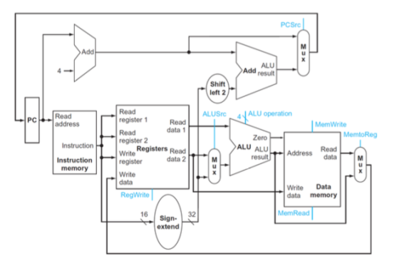

3, (4 points) For question#2, in the datapath as shown in Fig. 1, assume that one of the following control signals has a stuch-at-0 fault, meaning that the signal is always 0, regardless of its intended value. Which instruction(s) for the following five instructions (I1-15) will fail (cannot be executed)? Or all instructions can be executed successfully? Please justify your answer II: add Ssl, Ss2, Ss3 12: 1w Ss4, 4(Ss4) 13: addi Ss5, St3, 8 14: beq Stl, St2, loop 15: sw St2, 6(Ss2) (a) MemtoReg (b) PCSrc (c) MemWrite (d) ALUSrc
Homework Answers
(a)MemtoReg = 0 (only load word do write register after reading
from memory)
add $s1,$s2,$s3 (it will work correctly because its MemtoReg
=0)
lw $s4 ,4($s4) (it will not work correctly because its MemtoReg
=1)
addi $s5 ,$t3,8 (it will work correctly because its MemtoReg
=0)
beq $t1 ,$t2,loop (it will work correctly because its MemtoReg =X
(don't care))
sw $t2 ,6($s2) (it will work correctly because its MemtoReg =X
(don't care))
(b)PCSrc = 0 (only branch instructions need PC value to decide
target address)
add $s1,$s2,$s3 (it will work correctly because its PCSrc =0)
lw $s4 ,4($s4) (it will work correctly because its PCSrc =0)
addi $s5 ,$t3,8 (it will work correctly because its PCSrc =0)
beq $t1 ,$t2,loop (it will not work correctly because its PCSrc
=1)
sw $t2 ,6($s2) (it will work correctly because its PCSrc =0)
(c)MemWrite = 0 (only store word (sw) do memory write)
add $s1,$s2,$s3 (it will work correctly because its MemWrite
=0)
lw $s4 ,4($s4) (it will work correctly because its MemWrite
=0)
addi $s5 ,$t3,8 (it will work correctly because its MemWrite
=0)
beq $t1 ,$t2,loop (it will work correctly because its MemWrite
=0)
sw $t2 ,6($s2) (it will not work correctly because its MemWrite
=1)
(d)ALUSrc = 0
add $s1,$s2,$s3 (it will work correctly because its ALUSrc
=0)
lw $s4 ,4($s4) (it will not work correctly because its ALUSrc
=1)
addi $s5 ,$t3,8 (it will not work correctly because its ALUSrc
=1)
beq $t1 ,$t2,loop (it will work correctly because its ALUSrc
=0)
sw $t2 ,6($s2) (it will not work correctly because its ALUSrc
=1)
Add Answer to:
PCSrc Add ALU Add result Shift left 2 Read register 1Read Read register 2 Write register Write da...
Question 5 0.25 pts What is the value of the MemWrite control signal? Question 6 0.25 pts What is the value of the ALUSrc control signal? Add Add Sum--(1 4 Shift left 1 Branch MemRead Instruction [6-...
 Question 5 0.25 pts What is the value of the MemWrite control signal? Question 6 0.25 pts What is the value of the ALUSrc control signal? Add Add Sum--(1 4 Shift left 1 Branch MemRead Instruction [6-0] ControMemtoReg MemWrite ALUSrc RegWrite Instruction [19-15]Read Read register 1 Read Read data! PCaddress Instruction [24-20] Zero ALU ALU result register 2 Instruction 31-0 Instruction [11-7 Read1 Address data | Write Read register daiaALU | M Instruction memory Write data Registers Write Data data...
6. Consider a datapath similar to the one in figure below, but for a processor that only has one type of instruction: unconditional PC-relative branch. What would the cycle time be for this dat...
 6. Consider a datapath similar to the one in figure below, but for a processor that only has one type of instruction: unconditional PC-relative branch. What would the cycle time be for this datapath? PCSrc Add ALU Add result Shift +( left 2 Read register 1 ALUSrc, 4 ALU operation PCRead PC-address Read data 1 Registers Read data 2 MemWrite Zero ALU ALU-I Address MemtoReg Instruction register 2 Instruction | Write Read data-M register Write Lu memory Write Data data...
(o x Add Addresult ALU Shift left 2 Regst Branch MemRead Instruction (31-26) MemtoReg Controll ALUOP...
 (o x Add Addresult ALU Shift left 2 Regst Branch MemRead Instruction (31-26) MemtoReg Controll ALUOP MemWrite ALUSC RogWrite Instruction [25-21] Read register 1 Read Instruction (20-16) Read data 1 register 2 Write Read Instruction (15-11) Write data Registers PC Read address Zoro ALU ALU Instruction (31-0) Instruction memory result Address Read data register data 2 **039 -25 Write Data data memory Instruction (15-01 16 Sign- extend ALU control Instruction 15-01 With regards to the single cycle implementation (as shown...
3. Assume the processor data path show below. XE30 Add Add ALU result Shift left 2...
 3. Assume the processor data path show below. XE30 Add Add ALU result Shift left 2 RegDst Branch MemRead Instruction (31-26] RegSrc Control ALUOP Mem Write ALUSrc RegWrite PC Instruction (25-21) Read address Instruction (20-16] Instruction [31-0) Instruction instruction (15-11) memory Read register 1 Read data 1 Read register 2 Write Read register data 2 Write data Registers Zero ALU ALU result Read Address data OX OX3) 3x) Write Data data memory Instruction [15-0) 16 32 Sign- extend ALU control...
Assume that ‘slt $1, $2, $3’ is executed with the implementation in the picture. Identify the value of the 9-bit control...
 Assume that ‘slt $1, $2, $3’ is executed with the implementation
in the picture. Identify the value of the 9-bit control
signals.
Add u X ALU result 4 Add Shift left 2 RegDst Branch MemRead MemtoReg Control ALUOP Instruction [31-26 MemWrite ALUSRC RegWrite Instruction [25-21] Read register 1 Read Read PC address Instruction [20-16] data 1 Read Zero register 2 Instruction ALU ALU 31-0] Instruction memory Read data M Read Address Write result u M Instruction [15-11] register data 2...
Assume that ‘slt $1, $2, $3’ is executed with the implementation
in the picture. Identify the value of the 9-bit control
signals.
Add u X ALU result 4 Add Shift left 2 RegDst Branch MemRead MemtoReg Control ALUOP Instruction [31-26 MemWrite ALUSRC RegWrite Instruction [25-21] Read register 1 Read Read PC address Instruction [20-16] data 1 Read Zero register 2 Instruction ALU ALU 31-0] Instruction memory Read data M Read Address Write result u M Instruction [15-11] register data 2...
MCS) Add Addresult ALU Shift left 2 RegDst Branch MemRead MemtoReg Instruction (31-26] Control ALUOP MemWrite...
 MCS) Add Addresult ALU Shift left 2 RegDst Branch MemRead MemtoReg Instruction (31-26] Control ALUOP MemWrite ALUS RegWrite PC instruction (25-21] Instruction (20-16) Read address Instruction (31-0) Instruction memory Read register 1 Read Read data 1 register 2 Write Read Zoro ALU ALU result Address Read data instruction (15-11] register data 2 x3) Write data Registers Write Data data memory Instruction 15-01 16 Sign- extend ALU control Instruction (5-0) With regards to the single cycle implementation (as shown in the...
*For a clearer view of the datapath* Answer choices for all Consider the MIPS single cycle...
 *For a clearer view of the datapath*
Answer choices for all
Consider the MIPS single cycle datapath shown below. Select the correct control signals that will be generated by the control unit for the following instruction: andi $t0,$t1,4 Instruction (25-01 Shin Jump address (31-0) - left 2) 28 PC +4 [31-28) XCS result left 2 RegDst Jump Branch MemRead Instruction (31-26] MemtoReg Control ALUOP MemWrite ALUSrc RegWrite Instruction (25-21] PC Read address Read register 1 Read Instruction (20-16] Read data...
*For a clearer view of the datapath*
Answer choices for all
Consider the MIPS single cycle datapath shown below. Select the correct control signals that will be generated by the control unit for the following instruction: andi $t0,$t1,4 Instruction (25-01 Shin Jump address (31-0) - left 2) 28 PC +4 [31-28) XCS result left 2 RegDst Jump Branch MemRead Instruction (31-26] MemtoReg Control ALUOP MemWrite ALUSrc RegWrite Instruction (25-21] PC Read address Read register 1 Read Instruction (20-16] Read data...
Add 9 MUX 4 4 Addresult ALU Shift left 2 RegDst Branch MemRead Instruction (31-26) Control...
 Add 9 MUX 4 4 Addresult ALU Shift left 2 RegDst Branch MemRead Instruction (31-26) Control Memto Reg ALUOD MemWrite ALUSC RegWrite Instruction [25-21) Read PC Read address register 1 Read Instruction (20-16] MUX1 MUX Zero ALU ALU MUX3 M Instruction (31-0) Instruction memory Road Address data Read data 1 register 2 Write Read register data 2 Write data Registers result Instruction (15-11] Fox SX) Data Write data memory 16 32 Instruction (150) Sign- extend ALU control Instruction (5-0)
Add EX ALU Add dresult Shift left 2 Regst Branch MomRoad Instruction (31-26) MemtoReg Control ALUOO...
 Add EX ALU Add dresult Shift left 2 Regst Branch MomRoad Instruction (31-26) MemtoReg Control ALUOO MemWrite ALUST RegWrite instruction [25-21] Read register 1 Read instruction (20-16) Read data 1 register 2 Write Read data 2 instruction (15-11) register Write data Registers Read address Zero ALU ALU Instruction (31-0) Instruction memory result Address Read data Write Data data memory Instruction (15-01 16 32 Sign- extend ALU control Instruction (5-0) With regards to the single cycle implementation (as shown in the...
Question 4: Single Cycle Datapath Control (15 points) We wish to add the hardware support for...
 Question 4: Single Cycle Datapath Control (15 points) We wish to add the hardware support for a special R-type instruction jlr Jump and Link Register) to the single-cycle datapath below. Though this is an R-type instruction, but it is a special one that has the opcode being 000001 (instead of 000000), so the control unit will be able to differentiate this jlr instruction from the other R-type instructions and generate a special set of controls for this instruction. Opcode rs...
 Question 5 0.25 pts What is the value of the MemWrite control signal? Question 6 0.25 pts What is the value of the ALUSrc control signal? Add Add Sum--(1 4 Shift left 1 Branch MemRead Instruction [6-0] ControMemtoReg MemWrite ALUSrc RegWrite Instruction [19-15]Read Read register 1 Read Read data! PCaddress Instruction [24-20] Zero ALU ALU result register 2 Instruction 31-0 Instruction [11-7 Read1 Address data | Write Read register daiaALU | M Instruction memory Write data Registers Write Data data...
 6. Consider a datapath similar to the one in figure below, but for a processor that only has one type of instruction: unconditional PC-relative branch. What would the cycle time be for this datapath? PCSrc Add ALU Add result Shift +( left 2 Read register 1 ALUSrc, 4 ALU operation PCRead PC-address Read data 1 Registers Read data 2 MemWrite Zero ALU ALU-I Address MemtoReg Instruction register 2 Instruction | Write Read data-M register Write Lu memory Write Data data...
 (o x Add Addresult ALU Shift left 2 Regst Branch MemRead Instruction (31-26) MemtoReg Controll ALUOP MemWrite ALUSC RogWrite Instruction [25-21] Read register 1 Read Instruction (20-16) Read data 1 register 2 Write Read Instruction (15-11) Write data Registers PC Read address Zoro ALU ALU Instruction (31-0) Instruction memory result Address Read data register data 2 **039 -25 Write Data data memory Instruction (15-01 16 Sign- extend ALU control Instruction 15-01 With regards to the single cycle implementation (as shown...
 3. Assume the processor data path show below. XE30 Add Add ALU result Shift left 2 RegDst Branch MemRead Instruction (31-26] RegSrc Control ALUOP Mem Write ALUSrc RegWrite PC Instruction (25-21) Read address Instruction (20-16] Instruction [31-0) Instruction instruction (15-11) memory Read register 1 Read data 1 Read register 2 Write Read register data 2 Write data Registers Zero ALU ALU result Read Address data OX OX3) 3x) Write Data data memory Instruction [15-0) 16 32 Sign- extend ALU control...
 Assume that ‘slt $1, $2, $3’ is executed with the implementation
in the picture. Identify the value of the 9-bit control
signals.
Add u X ALU result 4 Add Shift left 2 RegDst Branch MemRead MemtoReg Control ALUOP Instruction [31-26 MemWrite ALUSRC RegWrite Instruction [25-21] Read register 1 Read Read PC address Instruction [20-16] data 1 Read Zero register 2 Instruction ALU ALU 31-0] Instruction memory Read data M Read Address Write result u M Instruction [15-11] register data 2...
Assume that ‘slt $1, $2, $3’ is executed with the implementation
in the picture. Identify the value of the 9-bit control
signals.
Add u X ALU result 4 Add Shift left 2 RegDst Branch MemRead MemtoReg Control ALUOP Instruction [31-26 MemWrite ALUSRC RegWrite Instruction [25-21] Read register 1 Read Read PC address Instruction [20-16] data 1 Read Zero register 2 Instruction ALU ALU 31-0] Instruction memory Read data M Read Address Write result u M Instruction [15-11] register data 2...
 MCS) Add Addresult ALU Shift left 2 RegDst Branch MemRead MemtoReg Instruction (31-26] Control ALUOP MemWrite ALUS RegWrite PC instruction (25-21] Instruction (20-16) Read address Instruction (31-0) Instruction memory Read register 1 Read Read data 1 register 2 Write Read Zoro ALU ALU result Address Read data instruction (15-11] register data 2 x3) Write data Registers Write Data data memory Instruction 15-01 16 Sign- extend ALU control Instruction (5-0) With regards to the single cycle implementation (as shown in the...
 *For a clearer view of the datapath*
Answer choices for all
Consider the MIPS single cycle datapath shown below. Select the correct control signals that will be generated by the control unit for the following instruction: andi $t0,$t1,4 Instruction (25-01 Shin Jump address (31-0) - left 2) 28 PC +4 [31-28) XCS result left 2 RegDst Jump Branch MemRead Instruction (31-26] MemtoReg Control ALUOP MemWrite ALUSrc RegWrite Instruction (25-21] PC Read address Read register 1 Read Instruction (20-16] Read data...
*For a clearer view of the datapath*
Answer choices for all
Consider the MIPS single cycle datapath shown below. Select the correct control signals that will be generated by the control unit for the following instruction: andi $t0,$t1,4 Instruction (25-01 Shin Jump address (31-0) - left 2) 28 PC +4 [31-28) XCS result left 2 RegDst Jump Branch MemRead Instruction (31-26] MemtoReg Control ALUOP MemWrite ALUSrc RegWrite Instruction (25-21] PC Read address Read register 1 Read Instruction (20-16] Read data...
 Add 9 MUX 4 4 Addresult ALU Shift left 2 RegDst Branch MemRead Instruction (31-26) Control Memto Reg ALUOD MemWrite ALUSC RegWrite Instruction [25-21) Read PC Read address register 1 Read Instruction (20-16] MUX1 MUX Zero ALU ALU MUX3 M Instruction (31-0) Instruction memory Road Address data Read data 1 register 2 Write Read register data 2 Write data Registers result Instruction (15-11] Fox SX) Data Write data memory 16 32 Instruction (150) Sign- extend ALU control Instruction (5-0)
 Add EX ALU Add dresult Shift left 2 Regst Branch MomRoad Instruction (31-26) MemtoReg Control ALUOO MemWrite ALUST RegWrite instruction [25-21] Read register 1 Read instruction (20-16) Read data 1 register 2 Write Read data 2 instruction (15-11) register Write data Registers Read address Zero ALU ALU Instruction (31-0) Instruction memory result Address Read data Write Data data memory Instruction (15-01 16 32 Sign- extend ALU control Instruction (5-0) With regards to the single cycle implementation (as shown in the...
 Question 4: Single Cycle Datapath Control (15 points) We wish to add the hardware support for a special R-type instruction jlr Jump and Link Register) to the single-cycle datapath below. Though this is an R-type instruction, but it is a special one that has the opcode being 000001 (instead of 000000), so the control unit will be able to differentiate this jlr instruction from the other R-type instructions and generate a special set of controls for this instruction. Opcode rs...
Most questions answered within 3 hours.
-
If you titrated 30.0 mL of 0.1 M HCl with 0.1 M NaOH, indicate
the approximate...
asked 6 minutes ago -
NADH passes electrons into the electron transport chain. List
the carriers that would receive the electrons,...
asked 14 minutes ago -
A cylindrical cable with a resistivity of 1.6x10⁻⁸ Ω·m and cross
sectional area of 3x10⁻⁵ m^2...
asked 14 minutes ago -
True or False.
A consumer with convex preferences who is indifferent between
the bundles (5,2) and...
asked 18 minutes ago -
A diamond's index of refraction for red light, 656 nm, is 2.410,
while that for blue...
asked 31 minutes ago -
Compare HPLC, SPE, and GC. Identify the differences, the
advantages, and the weaknesses of each method.
asked 32 minutes ago -
Characteristic x-rays emitted by potassium have a wavelength of
0.374 nm. What is the energy of...
asked 34 minutes ago -
there is a function to create two random numbers between 1 and
25 and a function...
asked 53 minutes ago -
At a certain temperature, the ?pKp for the decomposition of
H2SH2S is 0.832.0.832.
H2S(g)↽−−⇀H2(g)+S(g)H2S(g)↽−−⇀H2(g)+S(g)
Initially, only...
asked 46 minutes ago -
Part 1.C&A Fast Food has four activities in serving a
customer: greet customer, take order, process...
asked 53 minutes ago -
Which attribute allows you to specify a custom "thumbnail" for
multimedia elements?
asked 1 hour ago -
How much 0.1200 M sodium hydroxide solution is need to titrate
14 mL of a 0.100...
asked 1 hour ago