 , i) Determine the degree of
indeterminancy. ii) Calculate the support reactions. iii) Draw the
shear and moment diagrams.
, i) Determine the degree of
indeterminancy. ii) Calculate the support reactions. iii) Draw the
shear and moment diagrams.
Homework Answers


Add Answer to:
, i) Determine the degree of indeterminancy. ii) Calculate the support reactions. iii) Draw the s...
Please solve the following question using the force method. I need a full solution to check...
 Please solve the following question using the force method. I
need a full solution to check my work. Thanks Will rate thumbs
up.
6.2.For the following frames, i)Determine the degree of indeterminancy. ii)Calculate the support reactions. iii) Draw the moment and shear diagrams. a) EAC = 200Gpa, IAB = 250x 106 mm. IBC = 150x 106 mm" 10 KN/m 2m 70 KN 2m
Please solve the following question using the force method. I
need a full solution to check my work. Thanks Will rate thumbs
up.
6.2.For the following frames, i)Determine the degree of indeterminancy. ii)Calculate the support reactions. iii) Draw the moment and shear diagrams. a) EAC = 200Gpa, IAB = 250x 106 mm. IBC = 150x 106 mm" 10 KN/m 2m 70 KN 2m
Problem Determine the reactions and draw the shear and bending moment diagrams for the beams shown...
 Problem Determine the reactions and draw the shear and bending moment diagrams for the beams shown in Figs. P16.8-P16.14 by using the moment-distribution method 120 kN 120 kN 150 kN m--4 21 E 200 GPa 1- 500 (106 mm
1. Determine the reactions at the supports. Assume the support at A is fixed and B...
 1. Determine the reactions at the supports. Assume the support at A is fixed and B is a roller. Take E 200 GPa. The moment of inertia for each segment is given. Use principle of virtual work to find all required displacements. 25 kN 30 kN/m ГВ IAB 360(10) mm A TBC 180(10) mm 6 m 4 m
For the beam and loading shown in Figure A2: - a. Determine the support reactions b....
 For the beam and loading shown in Figure A2: - a. Determine the support reactions b. Draw the shear and bending moment diagrams c. Determine the maximum absolute value of shear force and bending moment P= 100 N P= 140 N w = 30 N/m A B 4 m 7 m 10 m 3 Figure A2.
Solve the following problems: (25 pts. each) Problem 1 Determine the support reactions then draw the...
 Solve the following problems: (25 pts. each) Problem 1 Determine the support reactions then draw the shear and bending moment diagrams for the beam loaded as shown below P !!K LR4 Problem 2 Determine the support reactions then draw the shear and bending moment diagrams for the beam loaded as shown below 구K 4.5 ,81 7 Problem 3 Determine the support reactions then draw the shear and bending moment diagrams for the beam loaded as shown below. Ptok Problem 4...
Find the Support Reactions and draw the Shear and Moment diagrams. RVM 2 (30 pts) w=1.2...
 Find the Support Reactions and draw the Shear and Moment diagrams.
RVM 2 (30 pts) w=1.2 kN/m and p-10 kN. L1 = 6 m and L2-3m. さ -D
Find the Support Reactions and draw the Shear and Moment diagrams.
RVM 2 (30 pts) w=1.2 kN/m and p-10 kN. L1 = 6 m and L2-3m. さ -D
solution step by step please Determine the support reactions and draw the shear and bending moment...
 solution step by step
please
Determine the support reactions and draw the shear and bending moment diagrams for the structure shown in Figure 1 by using the method of consistent deformations. X1 kN-I D 6 m x, kN/m 4m- 1-5 7 kN.m 4m Figure 1 X2= 606 kN/m
solution step by step
please
Determine the support reactions and draw the shear and bending moment diagrams for the structure shown in Figure 1 by using the method of consistent deformations. X1 kN-I D 6 m x, kN/m 4m- 1-5 7 kN.m 4m Figure 1 X2= 606 kN/m
1) Determine the reactions at the supports for the structures shown. The support at A is...
 1) Determine the reactions at the supports for the structures shown. The support at A is a Roller and the support at B is a Pin. 2.0 k/ft M 10 k- 3.0 k/ft 12 ft 25 k- 25k-Pokift 15 ft B! 1 F20ft- 2) 2 3 k/ft A beam is supported at points A, C, and E, and is loaded as shown. The support at A is fixed. The supports at C and E are rollers. Hinge-B ce Dl Hinge...
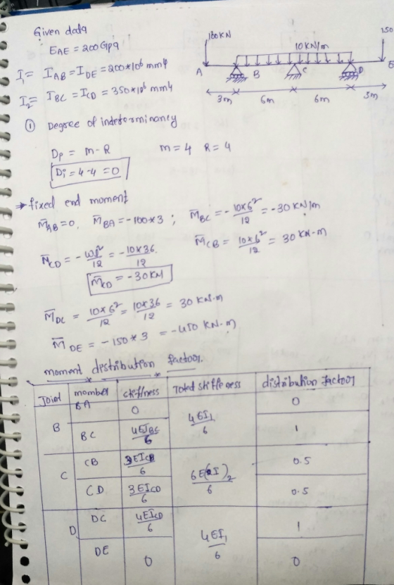
Part B) For the frame (no sidesway) below, determine the reactions and draw the shear and moment ...
 Part B) For the frame (no sidesway) below, determine the reactions and draw the shear and moment diagrams using the moment-distribution method of analysis. Joints A, B and E are fixed and all members are rigidly connected at C and D. You may perform the moment distribution by hand. E is constant, but I is as shown on the frame 50 kN 50 kN 4 m 6 kN/m 21 1.51 1.51 6 m 8 Part 3) Reanalyze the frame of...
i) state clearly the shear force and bending moment equations and ii) draw the shear force...
 i) state clearly the shear force and bending moment equations
and
ii) draw the shear force and bending moment diagrams.
50kN/m B 6m — 6m -
i) state clearly the shear force and bending moment equations
and
ii) draw the shear force and bending moment diagrams.
50kN/m B 6m — 6m -
 Please solve the following question using the force method. I
need a full solution to check my work. Thanks Will rate thumbs
up.
6.2.For the following frames, i)Determine the degree of indeterminancy. ii)Calculate the support reactions. iii) Draw the moment and shear diagrams. a) EAC = 200Gpa, IAB = 250x 106 mm. IBC = 150x 106 mm" 10 KN/m 2m 70 KN 2m
Please solve the following question using the force method. I
need a full solution to check my work. Thanks Will rate thumbs
up.
6.2.For the following frames, i)Determine the degree of indeterminancy. ii)Calculate the support reactions. iii) Draw the moment and shear diagrams. a) EAC = 200Gpa, IAB = 250x 106 mm. IBC = 150x 106 mm" 10 KN/m 2m 70 KN 2m
 Problem Determine the reactions and draw the shear and bending moment diagrams for the beams shown in Figs. P16.8-P16.14 by using the moment-distribution method 120 kN 120 kN 150 kN m--4 21 E 200 GPa 1- 500 (106 mm
 1. Determine the reactions at the supports. Assume the support at A is fixed and B is a roller. Take E 200 GPa. The moment of inertia for each segment is given. Use principle of virtual work to find all required displacements. 25 kN 30 kN/m ГВ IAB 360(10) mm A TBC 180(10) mm 6 m 4 m
 For the beam and loading shown in Figure A2: - a. Determine the support reactions b. Draw the shear and bending moment diagrams c. Determine the maximum absolute value of shear force and bending moment P= 100 N P= 140 N w = 30 N/m A B 4 m 7 m 10 m 3 Figure A2.
 Solve the following problems: (25 pts. each) Problem 1 Determine the support reactions then draw the shear and bending moment diagrams for the beam loaded as shown below P !!K LR4 Problem 2 Determine the support reactions then draw the shear and bending moment diagrams for the beam loaded as shown below 구K 4.5 ,81 7 Problem 3 Determine the support reactions then draw the shear and bending moment diagrams for the beam loaded as shown below. Ptok Problem 4...
 Find the Support Reactions and draw the Shear and Moment diagrams.
RVM 2 (30 pts) w=1.2 kN/m and p-10 kN. L1 = 6 m and L2-3m. さ -D
Find the Support Reactions and draw the Shear and Moment diagrams.
RVM 2 (30 pts) w=1.2 kN/m and p-10 kN. L1 = 6 m and L2-3m. さ -D
 solution step by step
please
Determine the support reactions and draw the shear and bending moment diagrams for the structure shown in Figure 1 by using the method of consistent deformations. X1 kN-I D 6 m x, kN/m 4m- 1-5 7 kN.m 4m Figure 1 X2= 606 kN/m
solution step by step
please
Determine the support reactions and draw the shear and bending moment diagrams for the structure shown in Figure 1 by using the method of consistent deformations. X1 kN-I D 6 m x, kN/m 4m- 1-5 7 kN.m 4m Figure 1 X2= 606 kN/m
 1) Determine the reactions at the supports for the structures shown. The support at A is a Roller and the support at B is a Pin. 2.0 k/ft M 10 k- 3.0 k/ft 12 ft 25 k- 25k-Pokift 15 ft B! 1 F20ft- 2) 2 3 k/ft A beam is supported at points A, C, and E, and is loaded as shown. The support at A is fixed. The supports at C and E are rollers. Hinge-B ce Dl Hinge...
 Part B) For the frame (no sidesway) below, determine the reactions and draw the shear and moment diagrams using the moment-distribution method of analysis. Joints A, B and E are fixed and all members are rigidly connected at C and D. You may perform the moment distribution by hand. E is constant, but I is as shown on the frame 50 kN 50 kN 4 m 6 kN/m 21 1.51 1.51 6 m 8 Part 3) Reanalyze the frame of...
 i) state clearly the shear force and bending moment equations
and
ii) draw the shear force and bending moment diagrams.
50kN/m B 6m — 6m -
i) state clearly the shear force and bending moment equations
and
ii) draw the shear force and bending moment diagrams.
50kN/m B 6m — 6m -
Most questions answered within 3 hours.
-
An MNE is this kind of industry when competition in one country
is essentially independent of...
asked 16 minutes ago -
. For this set of questions, determine what
proportion of a normal distribution is located betweeneach...
asked 51 minutes ago -
A college student is employed as a door-to-door newspaper
salesman. Historical data suggests that the student...
asked 1 hour ago -
MATLAB HW 11 problem using Switch Case and Input commands
Write a script file that calculates...
asked 1 hour ago -
Considering gravitational time dilation, calculate the time that
passes in Earth’s surface while 1 hour passes...
asked 2 hours ago -
Minitab Problem: Take the Lake Hume June rainfall data and find
use the processes outlined in...
asked 3 hours ago -
X Company is trying to decide whether to continue using old
equipment to make Product A...
asked 3 hours ago -
IN PYTHON ONLY !! Program 2: Re-work
program #5 (WeeklyHours) from the previous assignment such that...
asked 3 hours ago -
The average length of time between arrivals at a turnpike
toll-booth is 26 seconds. What is...
asked 5 hours ago -
(a) A piston at 6.1 atm contains a gas that occupies a volume of
3.5 L....
asked 6 hours ago -
Please answer true or false. Words
cannot be changed or added in to make it true...
asked 6 hours ago -
An empty test tube weighs 15.923 grams. Then,
MgCl2•6H2O is added into the test tube. After...
asked 6 hours ago