
Homework Answers
Add Answer to:
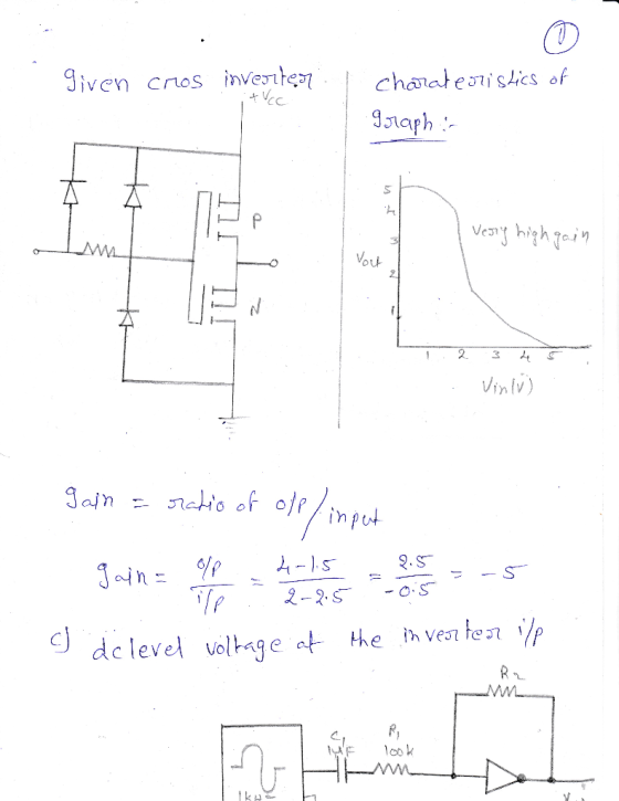
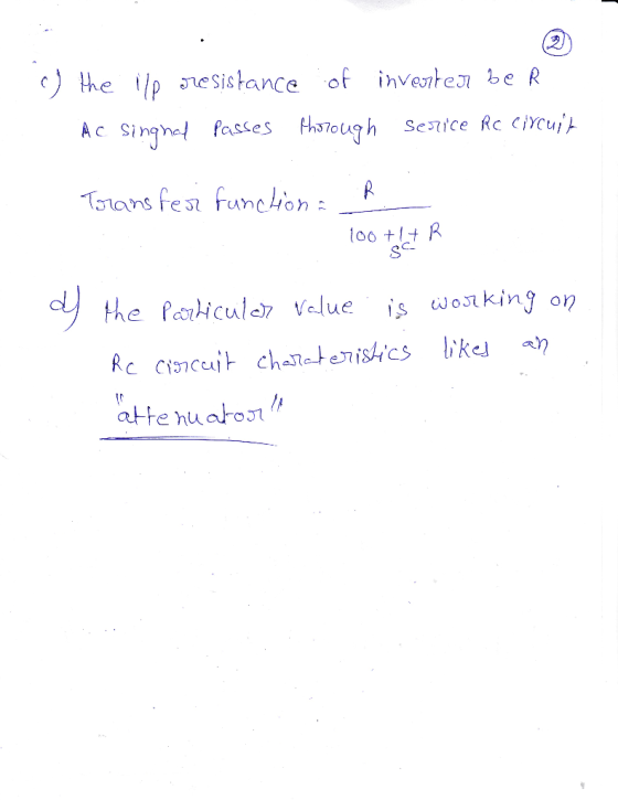
The CMOS inverter can be used as an amplifier because of the switching characteristics (see the f...
QUESTION (1) Transistor Mi in this common base amplifier circuit has the following characteristics: +Vc VTH...
 QUESTION (1) Transistor Mi in this common base amplifier circuit has the following characteristics: +Vc VTH =1 V Rp R, C. K 1 mA/V2 2 0.1 R Given: Vcc 2 mA, 10 V, lbias Ct C2 0, 5 k2, RD 2 k2 RI 10 k, R2 R (12 points) a) Determine the small signal gain, vo/Vin. (4 points) b) Determine the input resistance, Rin. (4 points) c) Determine the output resistance, Ro. Useful formulae: for n-channel MOSFET triode region =...
Inverting Amplifier Figure 4.2 shows the fundamental configuration of Op-Amp in which it is used as...
 Inverting Amplifier Figure 4.2 shows the fundamental configuration of Op-Amp in which it is used as an inverting amplifier. In this configuration the ratio, R2/R1 completely controls the effective gain of the amplifier and it can be verified that the output voltage is equal to Vo = - (R2/R1)Vin R2 100K Q-10V R1 Vinow 20K 1 2 7 V Vo 3 -10v Figure 4.2 Part 1 - Inverting Amp: Procedure 1. Construct the circuit of figure 4.2 using Op-Amp IC...
QUESTION 1 Anna the Audiophile has asked for your help to build an amplifier and filter...
 QUESTION 1 Anna the Audiophile has asked for your help to build an amplifier and filter to take small signals from her hifi system and amplify them so that she can drive her new subwoofer. The hifi system produces AC signals at varying frequencies with 250mVrms maximum magnitude Her subwoofer requires the signals to be 20 Vrms maximum magnitude. The signals that Anna is interested in are below 200 Hz. She would like the filter to attenuate signals at frequencies...
sedra smith book 7th edition chapter name is operational amplifier. question 12.1 to 12.10 I need...
 sedra smith book 7th edition chapter name is operational
amplifier. question 12.1 to 12.10 I need all solution with good
hand writing.
Problems 1075 Transistor Q3 WIL (um/um) 36/0.3 36/0.3 6/0.3 6/0.3 30/0.3 W/0.3 45/0.3 6/0.3 and A, if all devices are 0.3 m long, Q and Q2 are operated at overdrive voltages of 0.15-V magnitude, and Q is operated at Voy 0.2 V. Also, determine the op-amp output resistance 100 k2, C0.1 pF, G = 2 mA/V, R, =...
sedra smith book 7th edition chapter name is operational
amplifier. question 12.1 to 12.10 I need all solution with good
hand writing.
Problems 1075 Transistor Q3 WIL (um/um) 36/0.3 36/0.3 6/0.3 6/0.3 30/0.3 W/0.3 45/0.3 6/0.3 and A, if all devices are 0.3 m long, Q and Q2 are operated at overdrive voltages of 0.15-V magnitude, and Q is operated at Voy 0.2 V. Also, determine the op-amp output resistance 100 k2, C0.1 pF, G = 2 mA/V, R, =...
A common source amplifier circuit based on a single n-channel MOSFET is shown in Figure 4b. Assume that the transconductance gm-60 mS (equivalent to mA/ V) and drain source resistance, os,...
 A common source amplifier circuit based on a single n-channel MOSFET is shown in Figure 4b. Assume that the transconductance gm-60 mS (equivalent to mA/ V) and drain source resistance, os, is so large it may be neglected. 0) Calculate the open circuit voltage gain Av Yout/ Vis. i) The amplifier has a load of 10 k2. Determine the current gain Va. = 12 V 150k 4k3 Vout Vin 200k GND = 0 V Figure 4b a) State the name...
Vout should be a sinusoid signal of 12Vp-p Dc voltage to uA741 : +/-8.5V Please simulate...
 Vout should be a sinusoid signal of 12Vp-p
Dc voltage to uA741 : +/-8.5V
Please simulate as well
please help, im completely lost on this
this is all of the information
Experiment 5. RC Sinusoidal Oscillators PURPOSE: This laboratory provides an introduction to the background, analysis and design of sinusoidal oscillators using RC feedback networks and active devices to achieve the criteria for continuous oscillations to occur. EQUIPMENT REQUIRED : 1 Operational amplifier u.A741 1 CEU development station Resistors and...
Vout should be a sinusoid signal of 12Vp-p
Dc voltage to uA741 : +/-8.5V
Please simulate as well
please help, im completely lost on this
this is all of the information
Experiment 5. RC Sinusoidal Oscillators PURPOSE: This laboratory provides an introduction to the background, analysis and design of sinusoidal oscillators using RC feedback networks and active devices to achieve the criteria for continuous oscillations to occur. EQUIPMENT REQUIRED : 1 Operational amplifier u.A741 1 CEU development station Resistors and...
 QUESTION (1) Transistor Mi in this common base amplifier circuit has the following characteristics: +Vc VTH =1 V Rp R, C. K 1 mA/V2 2 0.1 R Given: Vcc 2 mA, 10 V, lbias Ct C2 0, 5 k2, RD 2 k2 RI 10 k, R2 R (12 points) a) Determine the small signal gain, vo/Vin. (4 points) b) Determine the input resistance, Rin. (4 points) c) Determine the output resistance, Ro. Useful formulae: for n-channel MOSFET triode region =...
 Inverting Amplifier Figure 4.2 shows the fundamental configuration of Op-Amp in which it is used as an inverting amplifier. In this configuration the ratio, R2/R1 completely controls the effective gain of the amplifier and it can be verified that the output voltage is equal to Vo = - (R2/R1)Vin R2 100K Q-10V R1 Vinow 20K 1 2 7 V Vo 3 -10v Figure 4.2 Part 1 - Inverting Amp: Procedure 1. Construct the circuit of figure 4.2 using Op-Amp IC...
 QUESTION 1 Anna the Audiophile has asked for your help to build an amplifier and filter to take small signals from her hifi system and amplify them so that she can drive her new subwoofer. The hifi system produces AC signals at varying frequencies with 250mVrms maximum magnitude Her subwoofer requires the signals to be 20 Vrms maximum magnitude. The signals that Anna is interested in are below 200 Hz. She would like the filter to attenuate signals at frequencies...
 sedra smith book 7th edition chapter name is operational
amplifier. question 12.1 to 12.10 I need all solution with good
hand writing.
Problems 1075 Transistor Q3 WIL (um/um) 36/0.3 36/0.3 6/0.3 6/0.3 30/0.3 W/0.3 45/0.3 6/0.3 and A, if all devices are 0.3 m long, Q and Q2 are operated at overdrive voltages of 0.15-V magnitude, and Q is operated at Voy 0.2 V. Also, determine the op-amp output resistance 100 k2, C0.1 pF, G = 2 mA/V, R, =...
sedra smith book 7th edition chapter name is operational
amplifier. question 12.1 to 12.10 I need all solution with good
hand writing.
Problems 1075 Transistor Q3 WIL (um/um) 36/0.3 36/0.3 6/0.3 6/0.3 30/0.3 W/0.3 45/0.3 6/0.3 and A, if all devices are 0.3 m long, Q and Q2 are operated at overdrive voltages of 0.15-V magnitude, and Q is operated at Voy 0.2 V. Also, determine the op-amp output resistance 100 k2, C0.1 pF, G = 2 mA/V, R, =...
 A common source amplifier circuit based on a single n-channel MOSFET is shown in Figure 4b. Assume that the transconductance gm-60 mS (equivalent to mA/ V) and drain source resistance, os, is so large it may be neglected. 0) Calculate the open circuit voltage gain Av Yout/ Vis. i) The amplifier has a load of 10 k2. Determine the current gain Va. = 12 V 150k 4k3 Vout Vin 200k GND = 0 V Figure 4b a) State the name...
 Vout should be a sinusoid signal of 12Vp-p
Dc voltage to uA741 : +/-8.5V
Please simulate as well
please help, im completely lost on this
this is all of the information
Experiment 5. RC Sinusoidal Oscillators PURPOSE: This laboratory provides an introduction to the background, analysis and design of sinusoidal oscillators using RC feedback networks and active devices to achieve the criteria for continuous oscillations to occur. EQUIPMENT REQUIRED : 1 Operational amplifier u.A741 1 CEU development station Resistors and...
Vout should be a sinusoid signal of 12Vp-p
Dc voltage to uA741 : +/-8.5V
Please simulate as well
please help, im completely lost on this
this is all of the information
Experiment 5. RC Sinusoidal Oscillators PURPOSE: This laboratory provides an introduction to the background, analysis and design of sinusoidal oscillators using RC feedback networks and active devices to achieve the criteria for continuous oscillations to occur. EQUIPMENT REQUIRED : 1 Operational amplifier u.A741 1 CEU development station Resistors and...
Most questions answered within 3 hours.
-
calculate the oxidation state of carbons C18H36O2 and
C18H36018
and then calculated the number of electrons...
asked 9 minutes ago -
Please respond to each of the below questions in a minimum of 5
well written paragraphs...
asked 3 minutes ago -
On January 1, Year 1, Brown Co. issued bonds with a face value
of $115,000, a...
asked 8 minutes ago -
It is better to optimize alpha by using trial and error methods
or by using methods...
asked 16 minutes ago -
An urn contains 39 red, 17 white and 30 blue marbles. A child
selects two marbles...
asked 19 minutes ago -
A student conducting this experiment weighs out 2.80 g of
CoCl2.6H2O.
For this part you will...
asked 26 minutes ago -
A cube, 100.0m on a side, has a total charge of 12.0 nC
distributed uniformly on...
asked 16 minutes ago -
Let's consider that two hockey players with equal mass, moving
with the same speed of 10...
asked 18 minutes ago -
Find the mid-range for the given sample data. Listed
below are the amounts of time (in...
asked 35 minutes ago -
If one wants to airlift a “thanksgiving’s” turkey (mass=3kg)
using a balloon. What would be the...
asked 31 minutes ago -
An institute reported that 63% of its members indicate that
lack of ethical culture within financial...
asked 33 minutes ago -
A proposal to your local city council in which you propose how
to use the money...
asked 42 minutes ago