
Homework Answers


Add Answer to:
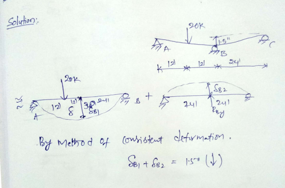
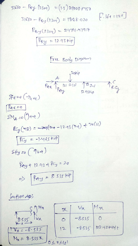
For the continuous beam shown, compute the support reactions using the method of consistent defor...
A simply supported beam as shown in the figure. The beam section is W18x211. The beam...
 A simply supported beam as shown in the figure. The beam section is W18x211. The beam must support its own weight and must carry the following loading: Super-imposed distributed dead load = 0.25 kip/ft Distributed live load = 1 kip/ft Concentrated dead load = 12 kip The beam span L = 26 ft and the distance of the concentrated load from the right support a=6 ft. Consider analy- sis of beam subjected to load combination 1.2 dead + 1.6 live....
Determine the reactions and draw the shear and bending momentdiagram. Use the method of consistent...
 Determine the reactions and draw the shear and bending moment
diagram. Use the method of consistent deformations and select the
reaction at the roller support to be the redundant.
Determine the reactions and draw the shear and bending moment
diagram. Use the method of consistent deformations and select the
reaction at the roller support to be the redundant.
Compute the reactions and draw the shear and bending moment diagrams continuous beam shown below (use...
 Compute the reactions and draw the shear and bending moment diagrams continuous beam shown below (use the force method) P 4 kips 2 k/ft I 9 fi 18 ft
16.6a) A simply supported beam is to span 15 ft. It will support a uniformly distributed load of ...
16.6a) A simply supported beam is to span 15 ft. It will support a uniformly distributed load of 2 kips/ft over the full span and a concentrated load of 60 kips at mid-span. What is the required plastic section modulus Zx? (Include self-weight) 16.6b) A simply supported beam is to span 15 ft. It will support a uniformly distributed load of 2 kips/ft over the full span and a concentrated load of 60 kips at mid-span. Deflection is not to...
Consider the beam subjected to a concentrated load consisting of 2.25 kips of dead load and...
 Consider the beam subjected to a concentrated load consisting of
2.25 kips of dead load and 5.55 kips of live load at point B. Find
maximum factored beam shear, moment, and deflection.
Consider the beam and loading given below. The beam is subjected to a concentrated load consisting of 2.25 kips of dead load and 5.55 kips of live load at point B. Neglect beam weight. You may use any information from the AISC Manual, a) Draw the general shape...
Consider the beam subjected to a concentrated load consisting of
2.25 kips of dead load and 5.55 kips of live load at point B. Find
maximum factored beam shear, moment, and deflection.
Consider the beam and loading given below. The beam is subjected to a concentrated load consisting of 2.25 kips of dead load and 5.55 kips of live load at point B. Neglect beam weight. You may use any information from the AISC Manual, a) Draw the general shape...
1-(25%) Draw shear and moment diagrams for the beam shown in Figure P-1 . Draw a sketch of the deflected shape. The spans are 30-ft long each (total of 90-ft), the concentrated loads are eac...
 1-(25%) Draw shear and moment diagrams for the beam shown in Figure P-1 . Draw a sketch of the deflected shape. The spans are 30-ft long each (total of 90-ft), the concentrated loads are each 120 kips, and placed at the center of left span and the free end. El is constant. Left support is a pin and the other two are roller supports. 120 kips 120 kips Figure P-1
1-(25%) Draw shear and moment diagrams for the beam shown...
1-(25%) Draw shear and moment diagrams for the beam shown in Figure P-1 . Draw a sketch of the deflected shape. The spans are 30-ft long each (total of 90-ft), the concentrated loads are each 120 kips, and placed at the center of left span and the free end. El is constant. Left support is a pin and the other two are roller supports. 120 kips 120 kips Figure P-1
1-(25%) Draw shear and moment diagrams for the beam shown...
5. Use the virtual work method using visual integration and only bending deformations to find the indicated deflec...
 5. Use the virtual work method using visual integration and only bending deformations to find the indicated deflections/rotations in each structure. Calculate the deflection at point D and the rotation at point B.I-1.46-10'mm and E 200 GPa. (20pts) 80 KN Moment release 60 KN 5 m 5 m 5 m 5 m 6. Use the virtual work method include both shear and bending deformations to determine the vertical deflection and rotation at point B. E-29,000 ksi; G 11000 ksi 1...
1. For the simply supported beam subjected to the loading shown, Derive equations for the shear...
 1. For the simply supported beam subjected to the loading shown, Derive equations for the shear force V and the bending moment M for any location in the beam. (Place the origin at point A.) a. b. Plot the shear-force and bending-moment diagrams for the beam using the derived functions c. Report the maximum bending moment and its location. 42 kips 6 kips/ft 10 ft 20 ft
16. Beam Deflection Using the method of progressive diagrams, find the centerline deflection for the given...
 16. Beam Deflection Using the method of progressive diagrams, find the centerline deflection for the given beam. Give the required values for each diagram (load, shear, moment slope(EI) and deflection) shown in the problem statement (see the pdf). 3 w 1 DATASET: 1 -2. Length A Length B Point Load P Uniform Load w Modulus of Elasticity Moment of Inertia 9 FT 10 FT 13 KIPS 1 KLF 29000 KSI 600 IN 4 -A- B- -- A - Correct Answer...
Problem 2: For the truss shown, compute all member forces using the method of consistent deformations...
 Problem 2: For the truss shown, compute all member forces using the method of consistent deformations by taking the force in member M6 (between joints 1 and 4) as redundant. Given: E-29,000 ksi and A-2.0 in2 A-2.0 in for all members. 20 kips 3 4. M4 M5 M6 10 ft uo M1 2 10 ft
 A simply supported beam as shown in the figure. The beam section is W18x211. The beam must support its own weight and must carry the following loading: Super-imposed distributed dead load = 0.25 kip/ft Distributed live load = 1 kip/ft Concentrated dead load = 12 kip The beam span L = 26 ft and the distance of the concentrated load from the right support a=6 ft. Consider analy- sis of beam subjected to load combination 1.2 dead + 1.6 live....
 Determine the reactions and draw the shear and bending moment
diagram. Use the method of consistent deformations and select the
reaction at the roller support to be the redundant.
Determine the reactions and draw the shear and bending moment
diagram. Use the method of consistent deformations and select the
reaction at the roller support to be the redundant.
 Compute the reactions and draw the shear and bending moment diagrams continuous beam shown below (use the force method) P 4 kips 2 k/ft I 9 fi 18 ft
 Consider the beam subjected to a concentrated load consisting of
2.25 kips of dead load and 5.55 kips of live load at point B. Find
maximum factored beam shear, moment, and deflection.
Consider the beam and loading given below. The beam is subjected to a concentrated load consisting of 2.25 kips of dead load and 5.55 kips of live load at point B. Neglect beam weight. You may use any information from the AISC Manual, a) Draw the general shape...
Consider the beam subjected to a concentrated load consisting of
2.25 kips of dead load and 5.55 kips of live load at point B. Find
maximum factored beam shear, moment, and deflection.
Consider the beam and loading given below. The beam is subjected to a concentrated load consisting of 2.25 kips of dead load and 5.55 kips of live load at point B. Neglect beam weight. You may use any information from the AISC Manual, a) Draw the general shape...
 1-(25%) Draw shear and moment diagrams for the beam shown in Figure P-1 . Draw a sketch of the deflected shape. The spans are 30-ft long each (total of 90-ft), the concentrated loads are each 120 kips, and placed at the center of left span and the free end. El is constant. Left support is a pin and the other two are roller supports. 120 kips 120 kips Figure P-1
1-(25%) Draw shear and moment diagrams for the beam shown...
1-(25%) Draw shear and moment diagrams for the beam shown in Figure P-1 . Draw a sketch of the deflected shape. The spans are 30-ft long each (total of 90-ft), the concentrated loads are each 120 kips, and placed at the center of left span and the free end. El is constant. Left support is a pin and the other two are roller supports. 120 kips 120 kips Figure P-1
1-(25%) Draw shear and moment diagrams for the beam shown...
 5. Use the virtual work method using visual integration and only bending deformations to find the indicated deflections/rotations in each structure. Calculate the deflection at point D and the rotation at point B.I-1.46-10'mm and E 200 GPa. (20pts) 80 KN Moment release 60 KN 5 m 5 m 5 m 5 m 6. Use the virtual work method include both shear and bending deformations to determine the vertical deflection and rotation at point B. E-29,000 ksi; G 11000 ksi 1...
 1. For the simply supported beam subjected to the loading shown, Derive equations for the shear force V and the bending moment M for any location in the beam. (Place the origin at point A.) a. b. Plot the shear-force and bending-moment diagrams for the beam using the derived functions c. Report the maximum bending moment and its location. 42 kips 6 kips/ft 10 ft 20 ft
 16. Beam Deflection Using the method of progressive diagrams, find the centerline deflection for the given beam. Give the required values for each diagram (load, shear, moment slope(EI) and deflection) shown in the problem statement (see the pdf). 3 w 1 DATASET: 1 -2. Length A Length B Point Load P Uniform Load w Modulus of Elasticity Moment of Inertia 9 FT 10 FT 13 KIPS 1 KLF 29000 KSI 600 IN 4 -A- B- -- A - Correct Answer...
 Problem 2: For the truss shown, compute all member forces using the method of consistent deformations by taking the force in member M6 (between joints 1 and 4) as redundant. Given: E-29,000 ksi and A-2.0 in2 A-2.0 in for all members. 20 kips 3 4. M4 M5 M6 10 ft uo M1 2 10 ft
Most questions answered within 3 hours.
-
Why are polymers not typically casted into products?
asked 5 minutes ago -
When rolling a die 129 times, what is the probability of rolling
a 6 no more...
asked 21 minutes ago -
4. A call option currently sells for $7.75. It has a strike
price of $85 and...
asked 10 minutes ago -
1.
You need to prepare 10.0 liters of an acid aqueous solution with a
pH of...
asked 13 minutes ago -
Along an aggregate supply curve, if the level of output is less
than the natural level...
asked 14 minutes ago -
By 2025, annual consumption in emerging markets will total $30
trillion and contribute more than ________...
asked 19 minutes ago -
At what point does reformation cease to be a viable option for
those who are oppressed...
asked 23 minutes ago -
Place letters corresponding to amounts in the proper order for
lightest to heaviest samples:
a) 2100...
asked 27 minutes ago -
Consider the multicore processor with 6 heterogeneous cores
labelled C1, C2, C3, C4, C5, and C6....
asked 30 minutes ago -
Document system components according to standards and procedures
(Implement and hand over system components) IT administrative
asked 30 minutes ago -
The college asked 700 students if they wanted a longer spring
break and 600 students said...
asked 29 minutes ago -
Determine the temperature (in Celsius) at which 1.00 mole of an
ideal gas will have a...
asked 54 minutes ago