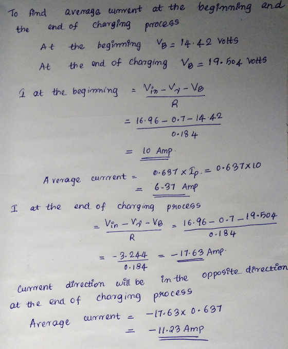
A half-wave rectifier is charging a battery, which has 12 V as its rated voltage. The battery is 85 % charged at the initial charging time. At the end of the charging period, the battery voltage is 11...
A half-wave rectifier is charging a battery, which has 12 V as
its rated voltage. The battery is 85 %
charged at the initial charging time. At the end of the charging
period, the battery voltage is 115 %
of the rated voltage. Calculate the resistance value to limit the
charging current to a maximum of
10 A as the worst case. Get the power dissipated by the resistor
under these conditions. Get the
average current at the beginning and the end of the charging
process. Consider a 12 Vrms voltage
source at 50 Hz.
Homework Answers

Add Answer to:
A half-wave rectifier is charging a battery, which has 12 V as its rated voltage. The battery is 85 % charged at the initial charging time. At the end of the charging period, the battery voltage is 11...
1. A full wave rectifier, used as a battery charger, is shown in the figure below....
 1. A full wave rectifier, used as a battery charger, is shown in the figure below. D4 Assume battery voltage, E 12 V, battery capacity 50 watt-hours, average charging current, Io-4 A, primary input voltage is 120 V rms, 60 Hz, and the transformers (primary-secondary) turns ratio 4:1. Calculate (a) the conduction angle of the diode, (b) the value of the current limiting resistance R, (c) the power rating of R, (d) the charging time in hours.
QUESTION 2 Half wave_rectifier_with_RL_source_load calc_source power A half-wave rectifier of the figure shown below has a...
 QUESTION 2 Half wave_rectifier_with_RL_source_load calc_source power A half-wave rectifier of the figure shown below has a 120 Vrms, 60 Hz ac source. The load is a series inductance, resistance, and dc source, with L = 120 mH, R = 12 , and Vdc = 48 V. Determine the power absorbed by the de voltage source. Select the one best answer from the choices given below. Wm. Versin(con (c) 76 W (d) 89 W (e) 120 W (a) 35 W (b)...
1. A half wave rectifier is supplied from a 100Vms source. For a load consisting of a 60V battery fed through a 2Ω resistor as shown in Fig. I 2Ω D+ + VR() bat Fig. 1 For the rectifier shown in Fig....
 1. A half wave rectifier is supplied from a 100Vms source. For a load consisting of a 60V battery fed through a 2Ω resistor as shown in Fig. I 2Ω D+ + VR() bat Fig. 1 For the rectifier shown in Fig. 1, determine (a) a time varying expression for the current flowing into the battery 70.7sine -30 25.1 154.9) (b) (c) the average power flow into the battery (574W) the average power dissipation in the resistor (617W) A half...
A half-wave rectifier has a 120 Vrms 60 HZ ac source. The load IS 50...
 Q1)A half-wave rectifier has a 120 Vrms 60 HZ ac source. The load IS 50 W. Determine the value of a filter capacitor to keep the peak-to-peak nipple across the load to less than 1.5V. Seled the one best answer from the choices given below(a) 410 UF (d) 3270 uF (b) 820 UF (e) 6540 UFQ2)A diode whose internal resistance is 200 is to supply power to a 1000 load from 110V (rms) source pf supply. Calculate(a) peak load current...
A battery with a terminal voltage of 145 V is charged by the rectifier in PART-A. The current is to be kept at 10 A. The rectifier parameters are: LDC= 1 mH, LAC = 10 mH (a) Calculate the firing angl...
 A battery with a terminal voltage of 145 V is charged by the
rectifier in PART-A. The current is to be kept at 10 A. The
rectifier parameters are: LDC= 1 mH, LAC = 10 mH
(a) Calculate the firing angle required.
(b) During the turn-off, the current Ibat is to be reduced at
the fastest possible rate. Calculate the maximum decay rate
possible when Ibat is at 10 A.
(10 MARKS) (5 marks) PART-A: Fig. 1(a) shows a single-phase,...
A battery with a terminal voltage of 145 V is charged by the
rectifier in PART-A. The current is to be kept at 10 A. The
rectifier parameters are: LDC= 1 mH, LAC = 10 mH
(a) Calculate the firing angle required.
(b) During the turn-off, the current Ibat is to be reduced at
the fastest possible rate. Calculate the maximum decay rate
possible when Ibat is at 10 A.
(10 MARKS) (5 marks) PART-A: Fig. 1(a) shows a single-phase,...
Use matlab to solve Project A half-wave diode rectifier shown in the following Fig. 1 is...
 Use matlab to solve
Project A half-wave diode rectifier shown in the following Fig. 1 is an electrical cirouit that coeverts AC voltage to DC voltage. The voltage of the source is y,Sin(utwhere -f in whicfis the frequency. The operation of the circuit is illustrated in Fig. 2 where the dashod line shows the source veltage and the solid line shows the voltage across the resistor Diode Time Fig. 1 In the first cycle, thediode is on (conductingcurrent)fromに0umi 4Atthstme thediodetums...
Use matlab to solve
Project A half-wave diode rectifier shown in the following Fig. 1 is an electrical cirouit that coeverts AC voltage to DC voltage. The voltage of the source is y,Sin(utwhere -f in whicfis the frequency. The operation of the circuit is illustrated in Fig. 2 where the dashod line shows the source veltage and the solid line shows the voltage across the resistor Diode Time Fig. 1 In the first cycle, thediode is on (conductingcurrent)fromに0umi 4Atthstme thediodetums...
D Question 2 10 pts A three phase full-bridge rectifier draws 12-kW from a power supply that has 150-V phase-to-phase voltage. The power factor is 0.77. What is the maximum (peak) value of the cur...
 D Question 2 10 pts A three phase full-bridge rectifier draws 12-kW from a power supply that has 150-V phase-to-phase voltage. The power factor is 0.77. What is the maximum (peak) value of the current delivered by the supply? 10 pts DI Question 3 A full bridge, square wave inverter supplies an RL load with R-7-Ohm and L-58-mH. The DC voltage is 90-V and the output waveform frequency is 60-Hz. What is the magnitude of the third harmonic of the...
Question 4. (a) A full-wave bridge rectifier power supply is powered from the secondary of a...
 Question 4. (a) A full-wave bridge rectifier power supply is powered from the secondary of a transformer which has a rms secondary voltage of 15.6V. The primary of the transformer is connected to a 50Hz, 230VRMS power supply. A 2700uF filter capacitor is used. A current of 1.5 Amp is drawn from the supply. (i) Sketch a schematic diagram of the setup. (ii) Calculate the mean de output voltage. Assume each power diode has a forward voltage drop of 1...
12. A series RC circuit is driven by a periodic square wave voltage V(t) with a period T=0.3 sec. V(t)0 for t<0. Aft...
 12. A series RC circuit is driven by a periodic square wave voltage V(t) with a period T=0.3 sec. V(t)0 for t<0. After t=0, the voltage alternates between 15 V and 0 V. Assume that R-40 , C-150 HF. We will call the voltage across the capacitor and the resistor Ve(t and Vr(t) respectively (a) Calculate the current I(t) in the circuit, the voltage Vc(t), and the power delivered by the driving source as a function of time for the...
12. A series RC circuit is driven by a periodic square wave voltage V(t) with a period T=0.3 sec. V(t) 0 for t<0. A...
 12. A series RC circuit is driven by a periodic square wave voltage V(t) with a period T=0.3 sec. V(t) 0 for t<0. After t=0, the voltage alternates between 15 V and 0 V. Assume that R-40 , C 150 HF. We will call the voltage across the capacitor and the resistor Ve(t) and Vr(t) respectively (c) The capacitor above is now replaced by an inductor whose inductance is 0.24 H. We call the voltage across the inductor VL(t) Calculate...
 1. A full wave rectifier, used as a battery charger, is shown in the figure below. D4 Assume battery voltage, E 12 V, battery capacity 50 watt-hours, average charging current, Io-4 A, primary input voltage is 120 V rms, 60 Hz, and the transformers (primary-secondary) turns ratio 4:1. Calculate (a) the conduction angle of the diode, (b) the value of the current limiting resistance R, (c) the power rating of R, (d) the charging time in hours.
 QUESTION 2 Half wave_rectifier_with_RL_source_load calc_source power A half-wave rectifier of the figure shown below has a 120 Vrms, 60 Hz ac source. The load is a series inductance, resistance, and dc source, with L = 120 mH, R = 12 , and Vdc = 48 V. Determine the power absorbed by the de voltage source. Select the one best answer from the choices given below. Wm. Versin(con (c) 76 W (d) 89 W (e) 120 W (a) 35 W (b)...
 1. A half wave rectifier is supplied from a 100Vms source. For a load consisting of a 60V battery fed through a 2Ω resistor as shown in Fig. I 2Ω D+ + VR() bat Fig. 1 For the rectifier shown in Fig. 1, determine (a) a time varying expression for the current flowing into the battery 70.7sine -30 25.1 154.9) (b) (c) the average power flow into the battery (574W) the average power dissipation in the resistor (617W) A half...
 Q1)A half-wave rectifier has a 120 Vrms 60 HZ ac source. The load IS 50 W. Determine the value of a filter capacitor to keep the peak-to-peak nipple across the load to less than 1.5V. Seled the one best answer from the choices given below(a) 410 UF (d) 3270 uF (b) 820 UF (e) 6540 UFQ2)A diode whose internal resistance is 200 is to supply power to a 1000 load from 110V (rms) source pf supply. Calculate(a) peak load current...
 A battery with a terminal voltage of 145 V is charged by the
rectifier in PART-A. The current is to be kept at 10 A. The
rectifier parameters are: LDC= 1 mH, LAC = 10 mH
(a) Calculate the firing angle required.
(b) During the turn-off, the current Ibat is to be reduced at
the fastest possible rate. Calculate the maximum decay rate
possible when Ibat is at 10 A.
(10 MARKS) (5 marks) PART-A: Fig. 1(a) shows a single-phase,...
A battery with a terminal voltage of 145 V is charged by the
rectifier in PART-A. The current is to be kept at 10 A. The
rectifier parameters are: LDC= 1 mH, LAC = 10 mH
(a) Calculate the firing angle required.
(b) During the turn-off, the current Ibat is to be reduced at
the fastest possible rate. Calculate the maximum decay rate
possible when Ibat is at 10 A.
(10 MARKS) (5 marks) PART-A: Fig. 1(a) shows a single-phase,...
 Use matlab to solve
Project A half-wave diode rectifier shown in the following Fig. 1 is an electrical cirouit that coeverts AC voltage to DC voltage. The voltage of the source is y,Sin(utwhere -f in whicfis the frequency. The operation of the circuit is illustrated in Fig. 2 where the dashod line shows the source veltage and the solid line shows the voltage across the resistor Diode Time Fig. 1 In the first cycle, thediode is on (conductingcurrent)fromに0umi 4Atthstme thediodetums...
Use matlab to solve
Project A half-wave diode rectifier shown in the following Fig. 1 is an electrical cirouit that coeverts AC voltage to DC voltage. The voltage of the source is y,Sin(utwhere -f in whicfis the frequency. The operation of the circuit is illustrated in Fig. 2 where the dashod line shows the source veltage and the solid line shows the voltage across the resistor Diode Time Fig. 1 In the first cycle, thediode is on (conductingcurrent)fromに0umi 4Atthstme thediodetums...
 D Question 2 10 pts A three phase full-bridge rectifier draws 12-kW from a power supply that has 150-V phase-to-phase voltage. The power factor is 0.77. What is the maximum (peak) value of the current delivered by the supply? 10 pts DI Question 3 A full bridge, square wave inverter supplies an RL load with R-7-Ohm and L-58-mH. The DC voltage is 90-V and the output waveform frequency is 60-Hz. What is the magnitude of the third harmonic of the...
 Question 4. (a) A full-wave bridge rectifier power supply is powered from the secondary of a transformer which has a rms secondary voltage of 15.6V. The primary of the transformer is connected to a 50Hz, 230VRMS power supply. A 2700uF filter capacitor is used. A current of 1.5 Amp is drawn from the supply. (i) Sketch a schematic diagram of the setup. (ii) Calculate the mean de output voltage. Assume each power diode has a forward voltage drop of 1...
 12. A series RC circuit is driven by a periodic square wave voltage V(t) with a period T=0.3 sec. V(t)0 for t<0. After t=0, the voltage alternates between 15 V and 0 V. Assume that R-40 , C-150 HF. We will call the voltage across the capacitor and the resistor Ve(t and Vr(t) respectively (a) Calculate the current I(t) in the circuit, the voltage Vc(t), and the power delivered by the driving source as a function of time for the...
 12. A series RC circuit is driven by a periodic square wave voltage V(t) with a period T=0.3 sec. V(t) 0 for t<0. After t=0, the voltage alternates between 15 V and 0 V. Assume that R-40 , C 150 HF. We will call the voltage across the capacitor and the resistor Ve(t) and Vr(t) respectively (c) The capacitor above is now replaced by an inductor whose inductance is 0.24 H. We call the voltage across the inductor VL(t) Calculate...
Most questions answered within 3 hours.
-
suppose there is a normally distributed population with a mean of
250 and a standard deviation...
asked 40 minutes ago -
Question Three
Suppose you as project manager are using the Waterfall
development methodology on a large...
asked 1 hour ago -
Which statement is not true about welfare in Canada?
A.Benefits typically vary based on one's ability...
asked 2 hours ago -
Please help me with FLOWCHART and UML diagram for class,
thank you!
#include <iostream>
#include <fstream>...
asked 2 hours ago -
3. Describe the “logic circuit” of the Lac operon. Which
proteins are bound or not to...
asked 2 hours ago -
Ayesha’s adjusted gross income is $60,000 in 2019. She donated a
piece of artwork with a...
asked 3 hours ago -
For Dijkstra’s shortest path algorithm:
a. Give the Big-O time for Dijkstra’s shortest path algorithm
and...
asked 3 hours ago -
Phosphorus violates the 'octet rule' in biological molecules,
forming more covalent bonds than expected based on...
asked 3 hours ago -
A 1.3 eV electron has a 10-4 probability of tunneling
through a 2.4 eV potential barrier....
asked 3 hours ago -
What is the one ingredient that is common to being successful
with all stakeholders?
profit
trust...
asked 3 hours ago -
Write an assembly language 32 bit program that reads in lines of
text by a .txt...
asked 3 hours ago -
what is the density ( in g/L) of hydrogen gas at 29 degrees C and a...
asked 3 hours ago