
Homework Answers


Add Answer to:
Building and testing basic combinational circuits using Verilog HDL Description: Build and test the following circuits using gate-level modeling in Verilog HDL 1.3-input majority function 2.Condition...
Building and testing basic combinational circuits using Verilog HDL Description: Build and test t...
Building and testing basic combinational circuits using Verilog HDL Description: Build and test the following circuits using gate-level modeling in Verilog HDL. 1. 3-input majority function. 2. Conditional inverter (see the table below: x - control input, y - data input). Do NOT use XOR gates for the implementation. x y Output 0 y 1 y' 3. Two-input multiplexer (see the table below: x,y - data inputs, z - control input). z Output 0 x 1 y 4. 1-bit half...
Please code the following in Verilog: Write the HDL gate-level hierarchical description of a four-bit adder-subtractor...
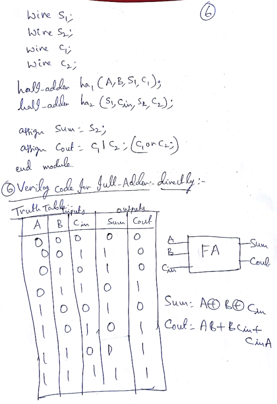
 Please code the following in Verilog:
Write the HDL gate-level hierarchical description of a four-bit adder-subtractor for unsigned binary numbers similar to the following circuit. You can instantiate the four-bit full adder described in the following example code Figure 4.13a, 4-Bit adder-subtractor without overflow Inputs: 4-Bit A, 4-Bit B, and Mode M (0-add/1-subtract) Interfaces: Carry Bits C1, C2, C3 Outputs: Carry C (1 Bit, C4), Sum S (4 bit) Bo A FA FA FA FA module Add half (input a,...
Please code the following in Verilog:
Write the HDL gate-level hierarchical description of a four-bit adder-subtractor for unsigned binary numbers similar to the following circuit. You can instantiate the four-bit full adder described in the following example code Figure 4.13a, 4-Bit adder-subtractor without overflow Inputs: 4-Bit A, 4-Bit B, and Mode M (0-add/1-subtract) Interfaces: Carry Bits C1, C2, C3 Outputs: Carry C (1 Bit, C4), Sum S (4 bit) Bo A FA FA FA FA module Add half (input a,...
number 4 and 5 please! PROBLEM STATEMENT A logic circuit is needed to add multi-bit binary...
 number 4 and 5 please!
PROBLEM STATEMENT A logic circuit is needed to add multi-bit binary numbers. A 2-level circuit that would add two four-bit numbers would have 9 inputs and five outputs. Although a 2-level SOP or POS circuit theoretically would be very fast, it has numerous drawbacks that make it impractical. The design would be very complex in terms of the number of logic gates. The number of inputs for each gate would challenge target technologies. Testing would...
number 4 and 5 please!
PROBLEM STATEMENT A logic circuit is needed to add multi-bit binary numbers. A 2-level circuit that would add two four-bit numbers would have 9 inputs and five outputs. Although a 2-level SOP or POS circuit theoretically would be very fast, it has numerous drawbacks that make it impractical. The design would be very complex in terms of the number of logic gates. The number of inputs for each gate would challenge target technologies. Testing would...
I need the following in verilog. Attached is also the test bench. CODE // Design a...
I need the following in verilog. Attached is also the test bench. CODE // Design a circuit that divides a 4-bit signed binary number (in) // by 3 to produce a 3-bit signed binary number (out). Note that // integer division rounds toward zero for both positive and negative // numbers (e.g., -5/3 is -1). module sdiv3(out, in); output [2:0] out; input [3:0] in; endmodule // sdiv3 TEST BENCH module test; // these are inputs to "circuit under test" reg...
 Please code the following in Verilog:
Write the HDL gate-level hierarchical description of a four-bit adder-subtractor for unsigned binary numbers similar to the following circuit. You can instantiate the four-bit full adder described in the following example code Figure 4.13a, 4-Bit adder-subtractor without overflow Inputs: 4-Bit A, 4-Bit B, and Mode M (0-add/1-subtract) Interfaces: Carry Bits C1, C2, C3 Outputs: Carry C (1 Bit, C4), Sum S (4 bit) Bo A FA FA FA FA module Add half (input a,...
Please code the following in Verilog:
Write the HDL gate-level hierarchical description of a four-bit adder-subtractor for unsigned binary numbers similar to the following circuit. You can instantiate the four-bit full adder described in the following example code Figure 4.13a, 4-Bit adder-subtractor without overflow Inputs: 4-Bit A, 4-Bit B, and Mode M (0-add/1-subtract) Interfaces: Carry Bits C1, C2, C3 Outputs: Carry C (1 Bit, C4), Sum S (4 bit) Bo A FA FA FA FA module Add half (input a,...
 number 4 and 5 please!
PROBLEM STATEMENT A logic circuit is needed to add multi-bit binary numbers. A 2-level circuit that would add two four-bit numbers would have 9 inputs and five outputs. Although a 2-level SOP or POS circuit theoretically would be very fast, it has numerous drawbacks that make it impractical. The design would be very complex in terms of the number of logic gates. The number of inputs for each gate would challenge target technologies. Testing would...
number 4 and 5 please!
PROBLEM STATEMENT A logic circuit is needed to add multi-bit binary numbers. A 2-level circuit that would add two four-bit numbers would have 9 inputs and five outputs. Although a 2-level SOP or POS circuit theoretically would be very fast, it has numerous drawbacks that make it impractical. The design would be very complex in terms of the number of logic gates. The number of inputs for each gate would challenge target technologies. Testing would...
Most questions answered within 3 hours.
-
last question i found wrong so downvoted so dont copy
paste or dont try if you...
asked 31 seconds ago -
A block sits on the floor. (a) What is the magnitude of the
frictional force on...
asked 24 minutes ago -
True or False: Spinal nerves emerging from the vertebral column
are ONLY motor OR sensory.
Select...
asked 4 minutes ago -
Thanks so much for the help! Please show all work.
A uniform solid disk with radius...
asked 4 minutes ago -
Please use Logicly!
Create a 4 bit sequential counter that is capable of counting up
or...
asked 12 minutes ago -
I1(t) and I2(t) describe the intensity of two
light waves.
I1(t)= 10sin(30t+π/4)
I2(t)=
10sin(30.4t+π)
Assume that...
asked 17 minutes ago -
A sample of steam with a mass of 0.501 g at a temperature of 100
∘C...
asked 23 minutes ago -
state one specific part from disability law such as ADA
(Americans with Disability Acts) or policy...
asked 25 minutes ago -
please simplify how vapor pressure lowering is related to a
rise in the boiling point solution
asked 39 minutes ago -
write a java program that does the following
Part one
Use a For loop to compute...
asked 37 minutes ago -
"A student in another class made a claim that many people are
now talking about outlawing...
asked 39 minutes ago -
Test the hypothesis using P-value approach. Be sure to verify
the requirements of the test.
H0:...
asked 1 hour ago