Need help with this. Circuits need to be done on Multisim. I will give you a good rating if you can help me out. Consider a two-diode AND logical gate circuit. Calculate and build a table showing the...
Need help with this. Circuits need to be done on Multisim. I will give you a good rating if you can help me out.
- Consider a two-diode AND logical gate circuit. Calculate and build a table showing the values of output voltages for 4 different combinations of input voltages.
- Simulate the circuit in Multisim for all above values of the input voltages, and observe the actual values of the output voltage. Add the simulation results to the table, compare, analyze, draw conclusions.
- Create a new circuit by connecting second similar AND gate to the output of the first and using another voltage as the second input to the second gate. Repeat simulation (2) with the constant another voltage at “high” and all four values of the first gate input voltage from the table in (1). Compare with (2) and draw conclusions
Homework Answers
Here is the simulations done in MULTISIM,
Let the input of AND gate be named as A and B. The output of AND gate is HIGH (1) only when both the inputs
A and B are HIGH together.
| A | B | A.B |
| 0 | 0 | 0 |
| 0 | 1 | 0 |
| 1 | 0 | 0 |
| 1 | 1 | 1 |
There are total four states, So there are total four simulation results. Note the 5V corresponds to 1 and 0V corresponds to 0

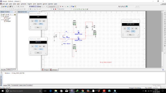

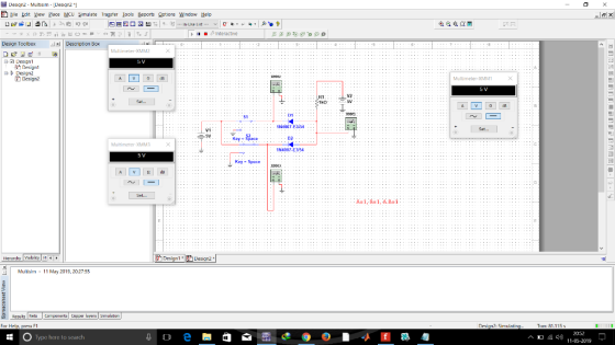
We can see that diode circuit obey's the AND gate truth table.
second part of question is not very much clear, however I will draw the schematic.

Please thumbs up
Add Answer to:
Need help with this. Circuits need to be done on Multisim. I will give you a good rating if you can help me out. Consider a two-diode AND logical gate circuit. Calculate and build a table showing the...
For your choice of input voltage, load resistor and the value of the ripple voltage (as percent of Vdc) design a circuit for the half-wave rectifier. Assuming the value of Van for the diode, calc...
 For your choice of input voltage, load resistor and the value of the ripple voltage (as percent of Vdc) design a circuit for the half-wave rectifier. Assuming the value of Van for the diode, calculate theoretically all parameters of the rectifier: Vp, Vdc, Idc, C, Isc, PIV and diode conducting interval. Simulate the designed circuit first without the capacitor filter and show on the graphs of the input, output and diode voltages and load and diode currents. Show on the...
done on pspice thank you Part IV: Diode Rectifiers Procedure: 1. Build the circuit model for...
 done on pspice thank you
Part IV: Diode Rectifiers Procedure: 1. Build the circuit model for full-wave diode rectifier in PSpice as shown in Fig. 4. The value of the load resistor is 10 k22. The input AC voltage source (VSIN in PSpice) is configured at 100 Hz and 20 V (peak-to- peak) in sinusoidal waveform. O 10K V.(t) V(A) A Figure 4. Circuit configuration for full-wave diode rectifier 2. Run the simulation and save the input and output voltage...
done on pspice thank you
Part IV: Diode Rectifiers Procedure: 1. Build the circuit model for full-wave diode rectifier in PSpice as shown in Fig. 4. The value of the load resistor is 10 k22. The input AC voltage source (VSIN in PSpice) is configured at 100 Hz and 20 V (peak-to- peak) in sinusoidal waveform. O 10K V.(t) V(A) A Figure 4. Circuit configuration for full-wave diode rectifier 2. Run the simulation and save the input and output voltage...
Could you please show me how I can drw those circuits. please using (NI Multisim 14)...
 Could you please show me how I can drw those circuits.
please using (NI Multisim 14)
Optocoupler Objectives Use an ohmmeter to determine the condition of the optoisolator. Observe the operation of an optocoupler. Determine the maximum frequency response of the optocoupler. Required Materials (1) Dual DC power supply (1) Function generator (1) Oscilloscope (2) Multimeters (1) Optocoupler (ECG3040) (1) 3.9ΚΩ resistor (1) 220 resistor Introduction An optoisolator is a hybrid integrated circuit that contains an LED on one side...
Could you please show me how I can drw those circuits.
please using (NI Multisim 14)
Optocoupler Objectives Use an ohmmeter to determine the condition of the optoisolator. Observe the operation of an optocoupler. Determine the maximum frequency response of the optocoupler. Required Materials (1) Dual DC power supply (1) Function generator (1) Oscilloscope (2) Multimeters (1) Optocoupler (ECG3040) (1) 3.9ΚΩ resistor (1) 220 resistor Introduction An optoisolator is a hybrid integrated circuit that contains an LED on one side...
need help for d,e,f OP-Amp Circuit R-20k Fig 1 1. Design an operational amplifier circuit using an LM741 op-amp an...
 need help for d,e,f
OP-Amp Circuit R-20k Fig 1 1. Design an operational amplifier circuit using an LM741 op-amp and a 10k the diagram shown in Fig 1 to produce the output voltage feedback resistor that represents Clearly write your ID number in Table 1 Table 1 Your ID Number 3775。73 . Set up the roquired gain numbers as follows and write them in Table 2 Ai- the last digit of your ID number+5 A2-the 2ed last digit of your...
need help for d,e,f
OP-Amp Circuit R-20k Fig 1 1. Design an operational amplifier circuit using an LM741 op-amp and a 10k the diagram shown in Fig 1 to produce the output voltage feedback resistor that represents Clearly write your ID number in Table 1 Table 1 Your ID Number 3775。73 . Set up the roquired gain numbers as follows and write them in Table 2 Ai- the last digit of your ID number+5 A2-the 2ed last digit of your...
Can you use Multisim or something similar. I got the truth table and design, but having...
 Can you use Multisim or something similar. I got the truth table
and design, but having a hard time with the actual wiring.
I need to see where each cable and light bulb go.
3.4. Multiplexer Multiplexers are very useful components in digital systems. They transfer a large number of information units over a smaller number of channels, (usually one channel) under the control of selection signals. Fig. 3 is a 4-line to l-line MUX. In this circuit, lo, 11, 12,...
Can you use Multisim or something similar. I got the truth table
and design, but having a hard time with the actual wiring.
I need to see where each cable and light bulb go.
3.4. Multiplexer Multiplexers are very useful components in digital systems. They transfer a large number of information units over a smaller number of channels, (usually one channel) under the control of selection signals. Fig. 3 is a 4-line to l-line MUX. In this circuit, lo, 11, 12,...
I NEED HELP WITH QUESTION #5 PLEASE AND CAN SOME FILL OUT THE FIRST ROW OF...
 I NEED HELP WITH QUESTION #5 PLEASE AND CAN SOME FILL OUT THE
FIRST ROW OF MY TABLE FOR 10Hz. I DONT KNOW HOW TO DO IT SO IF SOME
CAN FILL OUT THE FIRST TABLE AND SHOW ME HOW, THEN I CAN FINISH THE
REST. THANK YOU.
Reset Run / STOP 2uF Simulation Speed Current Speed 0 Power Brightness Current Circuit: 10Hz 1k New X S -15.933 V 100.165 ms 167.681 V capacitor, 2 UF 21.071 V resistor, 1...
I NEED HELP WITH QUESTION #5 PLEASE AND CAN SOME FILL OUT THE
FIRST ROW OF MY TABLE FOR 10Hz. I DONT KNOW HOW TO DO IT SO IF SOME
CAN FILL OUT THE FIRST TABLE AND SHOW ME HOW, THEN I CAN FINISH THE
REST. THANK YOU.
Reset Run / STOP 2uF Simulation Speed Current Speed 0 Power Brightness Current Circuit: 10Hz 1k New X S -15.933 V 100.165 ms 167.681 V capacitor, 2 UF 21.071 V resistor, 1...
I need a help with my lab, I write all data that get. 355 SERIES SINUSOIDAL...
 I need a help with my lab, I write all data that get.
355 SERIES SINUSOIDAL CIRCU CUITS neeseed 000 10 mH 10 kHz + R E-8V(Pp) V 1 kn Channel 2 Vert: 1 Vidiv Hor: 20 us/div. Channel 1 Vert: 1 Vidiv Hor: 20 us/div. FIG. 9.1 (b) After setting E to 8 V (p-p), determine the peak-to-peak voltage for Ve from chan- nel 2 and record in the top row of Table 9.1 Determine the phase angle 8,...
I need a help with my lab, I write all data that get.
355 SERIES SINUSOIDAL CIRCU CUITS neeseed 000 10 mH 10 kHz + R E-8V(Pp) V 1 kn Channel 2 Vert: 1 Vidiv Hor: 20 us/div. Channel 1 Vert: 1 Vidiv Hor: 20 us/div. FIG. 9.1 (b) After setting E to 8 V (p-p), determine the peak-to-peak voltage for Ve from chan- nel 2 and record in the top row of Table 9.1 Determine the phase angle 8,...
Need help with conclusion questions please 1. The objectives of this lab are (1) to determine...
 Need help with conclusion questions please
1. The objectives of this lab are (1) to determine the actual (A) total resistance of three resistors connected in series and compare it with the experimental (E ) value of total resistance (2) to determine the actual (A) total resistance of three resistors connected in parallel and compare it with the experimental(E ) value of total resistance II. Apparatus(Equipment): Voltage source, ammeter that measures current , voltmeter that measures voltage. II. Procedure: Three...
Need help with conclusion questions please
1. The objectives of this lab are (1) to determine the actual (A) total resistance of three resistors connected in series and compare it with the experimental (E ) value of total resistance (2) to determine the actual (A) total resistance of three resistors connected in parallel and compare it with the experimental(E ) value of total resistance II. Apparatus(Equipment): Voltage source, ammeter that measures current , voltmeter that measures voltage. II. Procedure: Three...
part II is what I need help one. part 1 is also attached for your reference...
 part II is what I need help one. part 1 is also
attached for your reference
Part II: Low Pass Filter contd. Noise Removal To observe the noise removal capabilities of a low -pass filter, we will add a second input to the system to simulate noise Step 1: Alter your Simulink model by adding another sine wave function and use a Sum block to add the inputs together as the new input to the system. The second sine function...
part II is what I need help one. part 1 is also
attached for your reference
Part II: Low Pass Filter contd. Noise Removal To observe the noise removal capabilities of a low -pass filter, we will add a second input to the system to simulate noise Step 1: Alter your Simulink model by adding another sine wave function and use a Sum block to add the inputs together as the new input to the system. The second sine function...
I only need help with the discussion there are many info that you do not need put I put just in ...
 I only need help with the discussion
there are many info that you do not need put I put just in
case as well as my data table.
please do it as soon as u can
Meauements ODeit1 Check2 Meaurements Checi3 Ced Check5 Check6 Measurements Check7 heck8 4058 33 536 1502 1035 979 119478 041 1.0319|0.554972| 64261| 153|15542033681 995781 5266566 1578807 298h 1631 119 1209430016 079096812 0.418135246 0,00032665 011890:004668155728441 0293237 1.291809502 1.22833 1.28 1952 -1116 4281 140616885511984206317 3346 8162 0.78...
I only need help with the discussion
there are many info that you do not need put I put just in
case as well as my data table.
please do it as soon as u can
Meauements ODeit1 Check2 Meaurements Checi3 Ced Check5 Check6 Measurements Check7 heck8 4058 33 536 1502 1035 979 119478 041 1.0319|0.554972| 64261| 153|15542033681 995781 5266566 1578807 298h 1631 119 1209430016 079096812 0.418135246 0,00032665 011890:004668155728441 0293237 1.291809502 1.22833 1.28 1952 -1116 4281 140616885511984206317 3346 8162 0.78...
 For your choice of input voltage, load resistor and the value of the ripple voltage (as percent of Vdc) design a circuit for the half-wave rectifier. Assuming the value of Van for the diode, calculate theoretically all parameters of the rectifier: Vp, Vdc, Idc, C, Isc, PIV and diode conducting interval. Simulate the designed circuit first without the capacitor filter and show on the graphs of the input, output and diode voltages and load and diode currents. Show on the...
 done on pspice thank you
Part IV: Diode Rectifiers Procedure: 1. Build the circuit model for full-wave diode rectifier in PSpice as shown in Fig. 4. The value of the load resistor is 10 k22. The input AC voltage source (VSIN in PSpice) is configured at 100 Hz and 20 V (peak-to- peak) in sinusoidal waveform. O 10K V.(t) V(A) A Figure 4. Circuit configuration for full-wave diode rectifier 2. Run the simulation and save the input and output voltage...
done on pspice thank you
Part IV: Diode Rectifiers Procedure: 1. Build the circuit model for full-wave diode rectifier in PSpice as shown in Fig. 4. The value of the load resistor is 10 k22. The input AC voltage source (VSIN in PSpice) is configured at 100 Hz and 20 V (peak-to- peak) in sinusoidal waveform. O 10K V.(t) V(A) A Figure 4. Circuit configuration for full-wave diode rectifier 2. Run the simulation and save the input and output voltage...
 Could you please show me how I can drw those circuits.
please using (NI Multisim 14)
Optocoupler Objectives Use an ohmmeter to determine the condition of the optoisolator. Observe the operation of an optocoupler. Determine the maximum frequency response of the optocoupler. Required Materials (1) Dual DC power supply (1) Function generator (1) Oscilloscope (2) Multimeters (1) Optocoupler (ECG3040) (1) 3.9ΚΩ resistor (1) 220 resistor Introduction An optoisolator is a hybrid integrated circuit that contains an LED on one side...
Could you please show me how I can drw those circuits.
please using (NI Multisim 14)
Optocoupler Objectives Use an ohmmeter to determine the condition of the optoisolator. Observe the operation of an optocoupler. Determine the maximum frequency response of the optocoupler. Required Materials (1) Dual DC power supply (1) Function generator (1) Oscilloscope (2) Multimeters (1) Optocoupler (ECG3040) (1) 3.9ΚΩ resistor (1) 220 resistor Introduction An optoisolator is a hybrid integrated circuit that contains an LED on one side...
 need help for d,e,f
OP-Amp Circuit R-20k Fig 1 1. Design an operational amplifier circuit using an LM741 op-amp and a 10k the diagram shown in Fig 1 to produce the output voltage feedback resistor that represents Clearly write your ID number in Table 1 Table 1 Your ID Number 3775。73 . Set up the roquired gain numbers as follows and write them in Table 2 Ai- the last digit of your ID number+5 A2-the 2ed last digit of your...
need help for d,e,f
OP-Amp Circuit R-20k Fig 1 1. Design an operational amplifier circuit using an LM741 op-amp and a 10k the diagram shown in Fig 1 to produce the output voltage feedback resistor that represents Clearly write your ID number in Table 1 Table 1 Your ID Number 3775。73 . Set up the roquired gain numbers as follows and write them in Table 2 Ai- the last digit of your ID number+5 A2-the 2ed last digit of your...
 Can you use Multisim or something similar. I got the truth table
and design, but having a hard time with the actual wiring.
I need to see where each cable and light bulb go.
3.4. Multiplexer Multiplexers are very useful components in digital systems. They transfer a large number of information units over a smaller number of channels, (usually one channel) under the control of selection signals. Fig. 3 is a 4-line to l-line MUX. In this circuit, lo, 11, 12,...
Can you use Multisim or something similar. I got the truth table
and design, but having a hard time with the actual wiring.
I need to see where each cable and light bulb go.
3.4. Multiplexer Multiplexers are very useful components in digital systems. They transfer a large number of information units over a smaller number of channels, (usually one channel) under the control of selection signals. Fig. 3 is a 4-line to l-line MUX. In this circuit, lo, 11, 12,...
 I NEED HELP WITH QUESTION #5 PLEASE AND CAN SOME FILL OUT THE
FIRST ROW OF MY TABLE FOR 10Hz. I DONT KNOW HOW TO DO IT SO IF SOME
CAN FILL OUT THE FIRST TABLE AND SHOW ME HOW, THEN I CAN FINISH THE
REST. THANK YOU.
Reset Run / STOP 2uF Simulation Speed Current Speed 0 Power Brightness Current Circuit: 10Hz 1k New X S -15.933 V 100.165 ms 167.681 V capacitor, 2 UF 21.071 V resistor, 1...
I NEED HELP WITH QUESTION #5 PLEASE AND CAN SOME FILL OUT THE
FIRST ROW OF MY TABLE FOR 10Hz. I DONT KNOW HOW TO DO IT SO IF SOME
CAN FILL OUT THE FIRST TABLE AND SHOW ME HOW, THEN I CAN FINISH THE
REST. THANK YOU.
Reset Run / STOP 2uF Simulation Speed Current Speed 0 Power Brightness Current Circuit: 10Hz 1k New X S -15.933 V 100.165 ms 167.681 V capacitor, 2 UF 21.071 V resistor, 1...
 I need a help with my lab, I write all data that get.
355 SERIES SINUSOIDAL CIRCU CUITS neeseed 000 10 mH 10 kHz + R E-8V(Pp) V 1 kn Channel 2 Vert: 1 Vidiv Hor: 20 us/div. Channel 1 Vert: 1 Vidiv Hor: 20 us/div. FIG. 9.1 (b) After setting E to 8 V (p-p), determine the peak-to-peak voltage for Ve from chan- nel 2 and record in the top row of Table 9.1 Determine the phase angle 8,...
I need a help with my lab, I write all data that get.
355 SERIES SINUSOIDAL CIRCU CUITS neeseed 000 10 mH 10 kHz + R E-8V(Pp) V 1 kn Channel 2 Vert: 1 Vidiv Hor: 20 us/div. Channel 1 Vert: 1 Vidiv Hor: 20 us/div. FIG. 9.1 (b) After setting E to 8 V (p-p), determine the peak-to-peak voltage for Ve from chan- nel 2 and record in the top row of Table 9.1 Determine the phase angle 8,...
 Need help with conclusion questions please
1. The objectives of this lab are (1) to determine the actual (A) total resistance of three resistors connected in series and compare it with the experimental (E ) value of total resistance (2) to determine the actual (A) total resistance of three resistors connected in parallel and compare it with the experimental(E ) value of total resistance II. Apparatus(Equipment): Voltage source, ammeter that measures current , voltmeter that measures voltage. II. Procedure: Three...
Need help with conclusion questions please
1. The objectives of this lab are (1) to determine the actual (A) total resistance of three resistors connected in series and compare it with the experimental (E ) value of total resistance (2) to determine the actual (A) total resistance of three resistors connected in parallel and compare it with the experimental(E ) value of total resistance II. Apparatus(Equipment): Voltage source, ammeter that measures current , voltmeter that measures voltage. II. Procedure: Three...
 part II is what I need help one. part 1 is also
attached for your reference
Part II: Low Pass Filter contd. Noise Removal To observe the noise removal capabilities of a low -pass filter, we will add a second input to the system to simulate noise Step 1: Alter your Simulink model by adding another sine wave function and use a Sum block to add the inputs together as the new input to the system. The second sine function...
part II is what I need help one. part 1 is also
attached for your reference
Part II: Low Pass Filter contd. Noise Removal To observe the noise removal capabilities of a low -pass filter, we will add a second input to the system to simulate noise Step 1: Alter your Simulink model by adding another sine wave function and use a Sum block to add the inputs together as the new input to the system. The second sine function...
 I only need help with the discussion
there are many info that you do not need put I put just in
case as well as my data table.
please do it as soon as u can
Meauements ODeit1 Check2 Meaurements Checi3 Ced Check5 Check6 Measurements Check7 heck8 4058 33 536 1502 1035 979 119478 041 1.0319|0.554972| 64261| 153|15542033681 995781 5266566 1578807 298h 1631 119 1209430016 079096812 0.418135246 0,00032665 011890:004668155728441 0293237 1.291809502 1.22833 1.28 1952 -1116 4281 140616885511984206317 3346 8162 0.78...
I only need help with the discussion
there are many info that you do not need put I put just in
case as well as my data table.
please do it as soon as u can
Meauements ODeit1 Check2 Meaurements Checi3 Ced Check5 Check6 Measurements Check7 heck8 4058 33 536 1502 1035 979 119478 041 1.0319|0.554972| 64261| 153|15542033681 995781 5266566 1578807 298h 1631 119 1209430016 079096812 0.418135246 0,00032665 011890:004668155728441 0293237 1.291809502 1.22833 1.28 1952 -1116 4281 140616885511984206317 3346 8162 0.78...
Most questions answered within 3 hours.
-
Accent Software faces the following conditions. All of these
support Accent’s use of a market-penetration pricing...
asked 51 minutes ago -
A mathematically inclined friend emails you the following
instructions: "Meet me in the cafeteria the first...
asked 53 minutes ago -
A monopoly sells in two countries . The demand curves in the two
countries are p1...
asked 1 hour ago -
A .15kg rubber ball is bounced off a wall. Before hitting the
wall, the ball moves...
asked 2 hours ago -
A manufacturing company preparing to build a new plant is
considering three potential locations for it....
asked 2 hours ago -
B. If compound Y has approximately the same values of solubility
in toluene as compound X,...
asked 3 hours ago -
Oscar Inc. has inventory in Japan valued at 39,051,000 Yen one
year ago. One year ago...
asked 3 hours ago -
If Canada suffered from "fundamental disequilibrium," and its
government choose not to devalue its currency, a...
asked 3 hours ago -
4. How many input & output Key Value Pairs are passed into,
and emitted out of...
asked 3 hours ago -
Why would your heart not function well if constructed of
skeletal muscle? What is the particular...
asked 3 hours ago -
Please respond to this essay question in full essay form for
Chemistry 1102 Organic and Biochemistry:...
asked 3 hours ago -
Determine the head loss and velocity of flow in a water supply main
of 15.0 cm...
asked 3 hours ago