
Homework Answers

Add Answer to:
For the circuit below, the output is at-15 V, and the input voltage is at +2 V if the input voltage is gradually lowered to -2 V, at what input voltage does the output switch from-15 V to +15 V (to 1...
For the circuit below, the output is at 15 V and the input voltage is at +2 V if the input voltage is gradually lowered to -2 V, at what input voltage does the output switch from +15 V to-15 V (to 1...
 For the circuit below, the output is at 15 V and the input voltage is at +2 V if the input voltage is gradually lowered to -2 V, at what input voltage does the output switch from +15 V to-15 V (to 1 % accuracy)? The op-amp has rail-to-rail swing, and a gain-bandwidth product of 3 MHz. The resistors used are r1 -1.5 k ohm and r2 22.8 k ohm r2 Vin 2 +2 V +15 V r1 f 1...
For the circuit below, the output is at -15 V, and the input voltage is at -2 V. if the input voltage is gradually raised to 2 V, at what input voltage does the output switch from-15 V to +15 V (to 1...
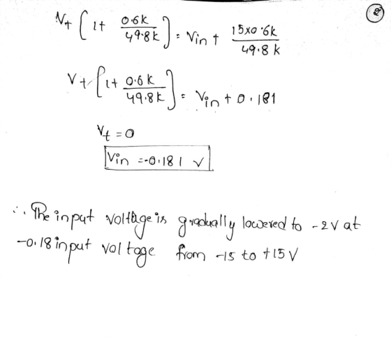
 For the circuit below, the output is at -15 V, and the input voltage is at -2 V. if the input voltage is gradually raised to 2 V, at what input voltage does the output switch from-15 V to +15 V (to 1% accuracy)? - The op-amp has rail-to-rail swing, and a gain-bandwidth product of 3 MHz. The resistors used are r1 1.3 k ohm and r2 37.7 k ohm r2 Vin 2/+2 V +15 V r1 o out f...
For the circuit below, calculate the time constant that defines the oscillation frequency of this circuit (i.e. the half period of the resulting oscillation T-1/(2fosc)), in seconds, to 1% accuracy....
 For the circuit below, calculate the time constant that defines the oscillation frequency of this circuit (i.e. the half period of the resulting oscillation T-1/(2fosc)), in seconds, to 1% accuracy. The op-amp has rail-to-rail swing, and a gain-bandwidth product of 3 MHz. The resistors used are r 3.0 k ohm, and the capacitor C 127.7 nF +15 V Vout 15 V Answer:
For the circuit below, calculate the time constant that defines the oscillation frequency of this circuit (i.e. the...
For the circuit below, calculate the time constant that defines the oscillation frequency of this circuit (i.e. the half period of the resulting oscillation T-1/(2fosc)), in seconds, to 1% accuracy. The op-amp has rail-to-rail swing, and a gain-bandwidth product of 3 MHz. The resistors used are r 3.0 k ohm, and the capacitor C 127.7 nF +15 V Vout 15 V Answer:
For the circuit below, calculate the time constant that defines the oscillation frequency of this circuit (i.e. the...
1. Find the ratio of the output voltage to the input voltage, Vo/Vin, in the circuit...
 1. Find the ratio of the output voltage to the input voltage, Vo/Vin, in the circuit shown. State your assumptions in using the ideal op-amp model. 15 k2 Vin 2. Find the output voltage Vo in the circuit shown assuming an ideal op-amp. State your assumptions in using the ideal op-amp model 15 k12 Vo . Find the voltage Vx and the output voltage Vo in the circuit shown assuming ideal op-amp 3 k2 1 V 6 kn 12 k2
For the amplifier circuits in Figs.3 and 7: a. Write an expression for the output voltage,...
 For the amplifier circuits in Figs.3 and 7:
a. Write an expression for the output voltage, vo, in terms of
the resistor symbols and the input voltage, vin.
---For the first circuit (Fig. 3), the feedback resistor is the
series combination of R2 and R3. Use both of these resistor symbols
in your expression.
-- For circuit 2 (Fig. 7), assume that vin = 5V and ignore
potentiometer R1 and C3.
b. Using resistor values and input voltage amplitudes, calculate...
For the amplifier circuits in Figs.3 and 7:
a. Write an expression for the output voltage, vo, in terms of
the resistor symbols and the input voltage, vin.
---For the first circuit (Fig. 3), the feedback resistor is the
series combination of R2 and R3. Use both of these resistor symbols
in your expression.
-- For circuit 2 (Fig. 7), assume that vin = 5V and ignore
potentiometer R1 and C3.
b. Using resistor values and input voltage amplitudes, calculate...
c) In estimating DC imperfections (input offset voltage, input offset current and the inverting amplifier with...
 c) In estimating DC imperfections (input offset voltage, input offset current and the inverting amplifier with nominal gain of -100 using 1 current) of an op-map, an and 10MQ resistors is implemented using the op-amp as shown in Fig 2(a) below R2 10MQ R 100k Vi Vo Figure 2(a): Inverting amplifier Measurements are conducted on the output voltage of the inverting amplifier under the following conditions: (i) the input (V) is open circuited and the output voltage is found to...
QUESTION 1. (15 points) GIVEN THE INPUT WAVEFORMS, ASSUMING VOLTAGE VOur IDEAL OP AMP. DRAN THE OUTPUT IVEN THE INPUT WAVE A. DRAW THE OUTPUT VOLTAGE Voor ON TOP OF INPUT SIGNAL V +V B. DRAW THE...
 QUESTION 1. (15 points) GIVEN THE INPUT WAVEFORMS, ASSUMING VOLTAGE VOur IDEAL OP AMP. DRAN THE OUTPUT IVEN THE INPUT WAVE A. DRAW THE OUTPUT VOLTAGE Voor ON TOP OF INPUT SIGNAL V +V B. DRAW THE OUTPUT VOLTAGE Vour ON TOP OF INPUT SIGNAL V +V +V Vi. C. HOW MUCH VOLTAGE WOULD HAVE TO BE AT THE POTENTIOMETER IN ORDER TO STABILIZE THE OUTPUT AT EXACTLY 0 VOLTS? +12 V +12 V V) Voltmeter 12 V 5V -12V...
Design a two-stage Op-Amp circuit as shown below to make the output voltage is vo=C1v1+C2v2, where...
 Design a two-stage Op-Amp circuit as shown below to make the
output voltage is
vo=C1v1+C2v2,
where C1 = 6 and C2 = 11.5, given that
Rf1=84 k?, and Rf2=21.5 k?.
a. Find the values of R1 and R2.
R1: _______ (k?); R2: _______ (k?)
b. Find the value of RS2:
_______(k?)
c. If v1=2.4 V and v2=3 V, find the output
voltage vo:
_______(V)
Rf Rf R2 02 Pi P2 Stage 1 Stage 2
Design a two-stage Op-Amp circuit as shown below to make the
output voltage is
vo=C1v1+C2v2,
where C1 = 6 and C2 = 11.5, given that
Rf1=84 k?, and Rf2=21.5 k?.
a. Find the values of R1 and R2.
R1: _______ (k?); R2: _______ (k?)
b. Find the value of RS2:
_______(k?)
c. If v1=2.4 V and v2=3 V, find the output
voltage vo:
_______(V)
Rf Rf R2 02 Pi P2 Stage 1 Stage 2
1. Consider a series RLC circuit with input voltage source Vin and the output voltage V,...
 1. Consider a series RLC circuit with input voltage source Vin and the output voltage V, taken as the resistor voltage. Assume the values are R = 10 kN, L = 10 mH, and C = 100 pF. a) Find the maximum output voltage and the frequency that it occurs. b) Determine the bandwidth and the quality factor and discuss the value of the quality factor.
Calculate using physics 6. A 9-V battery is connected through a switch to 2 resistors, R1...
 Calculate using physics
6. A 9-V battery is connected through a switch to 2 resistors, R1 = 15 Ohm and R2 = 23 Ohm. and an deal inductor L = 0.46 H as shown in the figure. The switch is initially open. Eight milliseconds after the switch is closed, what is the voltage cross the inductor?
Calculate using physics
6. A 9-V battery is connected through a switch to 2 resistors, R1 = 15 Ohm and R2 = 23 Ohm. and an deal inductor L = 0.46 H as shown in the figure. The switch is initially open. Eight milliseconds after the switch is closed, what is the voltage cross the inductor?
 For the circuit below, the output is at 15 V and the input voltage is at +2 V if the input voltage is gradually lowered to -2 V, at what input voltage does the output switch from +15 V to-15 V (to 1 % accuracy)? The op-amp has rail-to-rail swing, and a gain-bandwidth product of 3 MHz. The resistors used are r1 -1.5 k ohm and r2 22.8 k ohm r2 Vin 2 +2 V +15 V r1 f 1...
 For the circuit below, the output is at -15 V, and the input voltage is at -2 V. if the input voltage is gradually raised to 2 V, at what input voltage does the output switch from-15 V to +15 V (to 1% accuracy)? - The op-amp has rail-to-rail swing, and a gain-bandwidth product of 3 MHz. The resistors used are r1 1.3 k ohm and r2 37.7 k ohm r2 Vin 2/+2 V +15 V r1 o out f...
 For the circuit below, calculate the time constant that defines the oscillation frequency of this circuit (i.e. the half period of the resulting oscillation T-1/(2fosc)), in seconds, to 1% accuracy. The op-amp has rail-to-rail swing, and a gain-bandwidth product of 3 MHz. The resistors used are r 3.0 k ohm, and the capacitor C 127.7 nF +15 V Vout 15 V Answer:
For the circuit below, calculate the time constant that defines the oscillation frequency of this circuit (i.e. the...
For the circuit below, calculate the time constant that defines the oscillation frequency of this circuit (i.e. the half period of the resulting oscillation T-1/(2fosc)), in seconds, to 1% accuracy. The op-amp has rail-to-rail swing, and a gain-bandwidth product of 3 MHz. The resistors used are r 3.0 k ohm, and the capacitor C 127.7 nF +15 V Vout 15 V Answer:
For the circuit below, calculate the time constant that defines the oscillation frequency of this circuit (i.e. the...
 1. Find the ratio of the output voltage to the input voltage, Vo/Vin, in the circuit shown. State your assumptions in using the ideal op-amp model. 15 k2 Vin 2. Find the output voltage Vo in the circuit shown assuming an ideal op-amp. State your assumptions in using the ideal op-amp model 15 k12 Vo . Find the voltage Vx and the output voltage Vo in the circuit shown assuming ideal op-amp 3 k2 1 V 6 kn 12 k2
 For the amplifier circuits in Figs.3 and 7:
a. Write an expression for the output voltage, vo, in terms of
the resistor symbols and the input voltage, vin.
---For the first circuit (Fig. 3), the feedback resistor is the
series combination of R2 and R3. Use both of these resistor symbols
in your expression.
-- For circuit 2 (Fig. 7), assume that vin = 5V and ignore
potentiometer R1 and C3.
b. Using resistor values and input voltage amplitudes, calculate...
For the amplifier circuits in Figs.3 and 7:
a. Write an expression for the output voltage, vo, in terms of
the resistor symbols and the input voltage, vin.
---For the first circuit (Fig. 3), the feedback resistor is the
series combination of R2 and R3. Use both of these resistor symbols
in your expression.
-- For circuit 2 (Fig. 7), assume that vin = 5V and ignore
potentiometer R1 and C3.
b. Using resistor values and input voltage amplitudes, calculate...
 c) In estimating DC imperfections (input offset voltage, input offset current and the inverting amplifier with nominal gain of -100 using 1 current) of an op-map, an and 10MQ resistors is implemented using the op-amp as shown in Fig 2(a) below R2 10MQ R 100k Vi Vo Figure 2(a): Inverting amplifier Measurements are conducted on the output voltage of the inverting amplifier under the following conditions: (i) the input (V) is open circuited and the output voltage is found to...
 QUESTION 1. (15 points) GIVEN THE INPUT WAVEFORMS, ASSUMING VOLTAGE VOur IDEAL OP AMP. DRAN THE OUTPUT IVEN THE INPUT WAVE A. DRAW THE OUTPUT VOLTAGE Voor ON TOP OF INPUT SIGNAL V +V B. DRAW THE OUTPUT VOLTAGE Vour ON TOP OF INPUT SIGNAL V +V +V Vi. C. HOW MUCH VOLTAGE WOULD HAVE TO BE AT THE POTENTIOMETER IN ORDER TO STABILIZE THE OUTPUT AT EXACTLY 0 VOLTS? +12 V +12 V V) Voltmeter 12 V 5V -12V...
 Design a two-stage Op-Amp circuit as shown below to make the
output voltage is
vo=C1v1+C2v2,
where C1 = 6 and C2 = 11.5, given that
Rf1=84 k?, and Rf2=21.5 k?.
a. Find the values of R1 and R2.
R1: _______ (k?); R2: _______ (k?)
b. Find the value of RS2:
_______(k?)
c. If v1=2.4 V and v2=3 V, find the output
voltage vo:
_______(V)
Rf Rf R2 02 Pi P2 Stage 1 Stage 2
Design a two-stage Op-Amp circuit as shown below to make the
output voltage is
vo=C1v1+C2v2,
where C1 = 6 and C2 = 11.5, given that
Rf1=84 k?, and Rf2=21.5 k?.
a. Find the values of R1 and R2.
R1: _______ (k?); R2: _______ (k?)
b. Find the value of RS2:
_______(k?)
c. If v1=2.4 V and v2=3 V, find the output
voltage vo:
_______(V)
Rf Rf R2 02 Pi P2 Stage 1 Stage 2
 1. Consider a series RLC circuit with input voltage source Vin and the output voltage V, taken as the resistor voltage. Assume the values are R = 10 kN, L = 10 mH, and C = 100 pF. a) Find the maximum output voltage and the frequency that it occurs. b) Determine the bandwidth and the quality factor and discuss the value of the quality factor.
 Calculate using physics
6. A 9-V battery is connected through a switch to 2 resistors, R1 = 15 Ohm and R2 = 23 Ohm. and an deal inductor L = 0.46 H as shown in the figure. The switch is initially open. Eight milliseconds after the switch is closed, what is the voltage cross the inductor?
Calculate using physics
6. A 9-V battery is connected through a switch to 2 resistors, R1 = 15 Ohm and R2 = 23 Ohm. and an deal inductor L = 0.46 H as shown in the figure. The switch is initially open. Eight milliseconds after the switch is closed, what is the voltage cross the inductor?
Most questions answered within 3 hours.
-
9.) You are buying a car that cost $26,500. You make payments of
$412 each month...
asked 9 minutes ago -
. Suppose a discrete random variable has probability
distribution
P(x) = .2 if x = 0...
asked 1 hour ago -
Problem #1
The area between Z = 0 and Z = 2.50
The area between Z...
asked 25 minutes ago -
Under the influence of its drive force, a snowmobile is moving
at a constant velocity along...
asked 1 hour ago -
Why do organizations decline? What steps can top
management take to halt, decline, and restore organizational...
asked 1 hour ago -
What mechanisms Drive speciation??
(I.e. what was Dawins theory on the orgin of species, and how...
asked 3 hours ago -
The manager at a car assembly plant believes that the mean
assembly time for a car...
asked 4 hours ago -
Which of the following is true of electron capture?
A) It decreases the nuclide's mass number...
asked 5 hours ago -
Assuming an efficiency of 43.10%, calculate the actual yield of
magnesium nitrate formed from 114.9 g...
asked 6 hours ago -
The highly pathogenic bacterium Clostridium
perfringens causes gangrene, a disease that results in the
destruction of...
asked 8 hours ago -
In the context of situation analysis, which of the following is
a category for analysis in...
asked 8 hours ago -
In a study of the gas phase decomposition of sulfuryl chloride
at 600 K SO2Cl2(g)SO2(g) +...
asked 8 hours ago