
Homework Answers


Add Answer to:
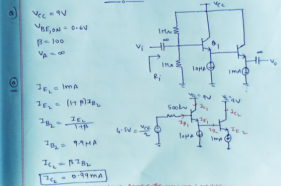
2. For the follower circuit below, KNOWN AS A Darlington pair, let Vcc 9V VBEON0.6V, and B100, VA for both transist...
The follower circuit is known as a Darlington pair. Let VCC=3V, β=10, VBE,ON=0.6V, and VA=∞ for both transistors. a) Com...
 The follower circuit is known as a Darlington pair. Let
VCC=3V, β=10, VBE,ON=0.6V, and
VA=∞ for both transistors.
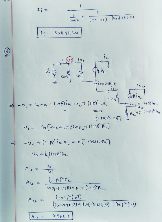
a) Compute Ri1, Ri2, and
Rout.
b) Find the small-signal voltage gain, .
We were unable to transcribe this imageVec Ri2 2k Rout REloss o.SmA o5mA Ri1 Rat
Vec Ri2 2k Rout REloss o.SmA o5mA Ri1 Rat
The follower circuit is known as a Darlington pair. Let
VCC=3V, β=10, VBE,ON=0.6V, and
VA=∞ for both transistors.
a) Compute Ri1, Ri2, and
Rout.
b) Find the small-signal voltage gain, .
We were unable to transcribe this imageVec Ri2 2k Rout REloss o.SmA o5mA Ri1 Rat
Vec Ri2 2k Rout REloss o.SmA o5mA Ri1 Rat
Vce Vec RI Vi ci HH QI C2 Vo R2 RL Partial Representation Darlington Emitter Follower...
 Vce Vec RI Vi ci HH QI C2 Vo R2 RL Partial Representation Darlington Emitter Follower of CE Amp Fig. 1.3 Q. 1.3. (CLO 1(C4)) (4) For the CE amplifier in Fig. 1.3. Vcc is 12V, Rc is 1k12, re' is 52. For the Darlington pair, Ri is 10k 2. R2 is 22k 2. RL is 82. Vcc is 12V and B is 100 for each Q. Neglect input impedance of base. Investigate the Av of the CE amplifier. Av...
This direct coupled emitter follower amplifier using a reference current mirror to produce a blasttent for...
 This direct coupled emitter follower amplifier using a reference current mirror to produce a blasttent for the di transistor The parameters for the circuit are as follows: . Vcc = -Ves = 5V • All transistors. Qı, Q2, Qs, are matched with the following parameters + 8 = 100 , Is = 10- A (Hints: You must solve for for all transistors. You may need to lerate once or twice to solve the recent with the foresistor in the Qiraulties...
2. In the following current mirror circuit, Vcc -10V, and the three transistors, Q1, Q2, Q3, have...
 2. In the following current mirror circuit, Vcc -10V, and the three transistors, Q1, Q2, Q3, have the same saturation current (i.e.,IssIs), and with V for active mode is 0.7V. Then, the three beta values are given by: β91-100, ßQ2-50, and ßQ3-200. The thermal voltage is ντ-25mV. Assuming that you need an output current of i1mA: ref db (a) Find the collector, base, and emitter current for all three Q1 O2 transistors when ia 1mA. (b) Find the refern ie....
It is just the question 4 needs to be solved. Mind the changes in question 4. Question 4 1 pts Consider practice questio...
 It is just the question 4
needs to be solved. Mind the changes in question 4.
Question 4 1 pts Consider practice question 3.4. The resistor RL is changed to 1.9 kilo-ohms. Solve part (a) of the question to find resistor R in kilo-ohms. 3.4. For the emitter follower in the figure below, given Vcc = 15 V, Vee=-15 V, Ri = 1 kQ and B= 100 for all the transistors. In the following calculations assume VCEsat= 0.2 V and...
It is just the question 4
needs to be solved. Mind the changes in question 4.
Question 4 1 pts Consider practice question 3.4. The resistor RL is changed to 1.9 kilo-ohms. Solve part (a) of the question to find resistor R in kilo-ohms. 3.4. For the emitter follower in the figure below, given Vcc = 15 V, Vee=-15 V, Ri = 1 kQ and B= 100 for all the transistors. In the following calculations assume VCEsat= 0.2 V and...
3.1. For the BJT differential pair configuration shown below, assume the input transistor beta is very large. Then...
 3.1. For the BJT differential pair configuration shown below,
assume the input transistor beta is very large.
Then find the differential signal vd = vB1 − vB2 sufficient to
cause:
3.2. A differential amplifier resembling that below uses I =
200μA, RC = 10kohm and VCC = 3V. Assume beta is very large
3.4.For the emitter follower in the figure below, given VCC =
15 V, VEE = −15 V, RL = 1 kohm and beta = 100 for all...
3.1. For the BJT differential pair configuration shown below,
assume the input transistor beta is very large.
Then find the differential signal vd = vB1 − vB2 sufficient to
cause:
3.2. A differential amplifier resembling that below uses I =
200μA, RC = 10kohm and VCC = 3V. Assume beta is very large
3.4.For the emitter follower in the figure below, given VCC =
15 V, VEE = −15 V, RL = 1 kohm and beta = 100 for all...
Consider the BJT circuit below with Qi and Q2 being identical transistors with Bac oc 50....
 Consider the BJT circuit below with Qi and Q2 being identical transistors with Bac oc 50. Assume a Vcc of 10 volts. 10 kS2 21 R6 C. 22 k? 4.7 k? a) Do a DC analysis on the Qi circuit and solve all B, C and E terminal voltages and currents. Use the quick analysis method after checking if the loading of R4 and R6 is acceptable b) Do a DC analysis on the Q2 circuit and solve all B,...
Consider the BJT circuit below with Qi and Q2 being identical transistors with Bac oc 50....
 Consider the BJT circuit below with Qi and Q2 being identical transistors with Bac oc 50. Assume a Vcc of 10 volts. 10 kS2 21 R6 C. 22 kΩ 4.7 kΩ a) Do a DC analysis on the Qi circuit and solve all B, C and E terminal voltages and currents. Use the quick analysis method after checking if the loading of R4 and R6 is acceptable b) Do a DC analysis on the Q2 circuit and solve all B,...
2. The circuit below is an emitter follower (the output is taken from the emitter and...
 2. The circuit below is an emitter follower (the output is taken from the emitter and its voltage follows the input voltage). VBE-0.7, Vt-25mV, and . a) Find the current IE to make the Gain voſvi= 0.7 v/v c) Find the value of R3 to make IE. d) Find Zin and Zout.
4. Consider the BJT cascade amplifier shown below Vcc 18V R1 3.3ko 15uF r Vo RL...
 4. Consider the BJT cascade amplifier shown below Vcc 18V R1 3.3ko 15uF r Vo RL B 150 Rsa 500? 56k? Vi B 150 C1 CE 2.2k? a) Find the DC collector current (approximately the same in both transistors). b) Find the input impedance, output impedance, and no-load voltage gain. c) Find the Av, Avs, and Ai d) Estimate the lower cutoff frequency e) Why does this amplifier have better high-frequency performance thana common-emitter built using the same type of...
 The follower circuit is known as a Darlington pair. Let
VCC=3V, β=10, VBE,ON=0.6V, and
VA=∞ for both transistors.
a) Compute Ri1, Ri2, and
Rout.
b) Find the small-signal voltage gain, .
We were unable to transcribe this imageVec Ri2 2k Rout REloss o.SmA o5mA Ri1 Rat
Vec Ri2 2k Rout REloss o.SmA o5mA Ri1 Rat
The follower circuit is known as a Darlington pair. Let
VCC=3V, β=10, VBE,ON=0.6V, and
VA=∞ for both transistors.
a) Compute Ri1, Ri2, and
Rout.
b) Find the small-signal voltage gain, .
We were unable to transcribe this imageVec Ri2 2k Rout REloss o.SmA o5mA Ri1 Rat
Vec Ri2 2k Rout REloss o.SmA o5mA Ri1 Rat
 Vce Vec RI Vi ci HH QI C2 Vo R2 RL Partial Representation Darlington Emitter Follower of CE Amp Fig. 1.3 Q. 1.3. (CLO 1(C4)) (4) For the CE amplifier in Fig. 1.3. Vcc is 12V, Rc is 1k12, re' is 52. For the Darlington pair, Ri is 10k 2. R2 is 22k 2. RL is 82. Vcc is 12V and B is 100 for each Q. Neglect input impedance of base. Investigate the Av of the CE amplifier. Av...
 This direct coupled emitter follower amplifier using a reference current mirror to produce a blasttent for the di transistor The parameters for the circuit are as follows: . Vcc = -Ves = 5V • All transistors. Qı, Q2, Qs, are matched with the following parameters + 8 = 100 , Is = 10- A (Hints: You must solve for for all transistors. You may need to lerate once or twice to solve the recent with the foresistor in the Qiraulties...
 2. In the following current mirror circuit, Vcc -10V, and the three transistors, Q1, Q2, Q3, have the same saturation current (i.e.,IssIs), and with V for active mode is 0.7V. Then, the three beta values are given by: β91-100, ßQ2-50, and ßQ3-200. The thermal voltage is ντ-25mV. Assuming that you need an output current of i1mA: ref db (a) Find the collector, base, and emitter current for all three Q1 O2 transistors when ia 1mA. (b) Find the refern ie....
 It is just the question 4
needs to be solved. Mind the changes in question 4.
Question 4 1 pts Consider practice question 3.4. The resistor RL is changed to 1.9 kilo-ohms. Solve part (a) of the question to find resistor R in kilo-ohms. 3.4. For the emitter follower in the figure below, given Vcc = 15 V, Vee=-15 V, Ri = 1 kQ and B= 100 for all the transistors. In the following calculations assume VCEsat= 0.2 V and...
It is just the question 4
needs to be solved. Mind the changes in question 4.
Question 4 1 pts Consider practice question 3.4. The resistor RL is changed to 1.9 kilo-ohms. Solve part (a) of the question to find resistor R in kilo-ohms. 3.4. For the emitter follower in the figure below, given Vcc = 15 V, Vee=-15 V, Ri = 1 kQ and B= 100 for all the transistors. In the following calculations assume VCEsat= 0.2 V and...
 3.1. For the BJT differential pair configuration shown below,
assume the input transistor beta is very large.
Then find the differential signal vd = vB1 − vB2 sufficient to
cause:
3.2. A differential amplifier resembling that below uses I =
200μA, RC = 10kohm and VCC = 3V. Assume beta is very large
3.4.For the emitter follower in the figure below, given VCC =
15 V, VEE = −15 V, RL = 1 kohm and beta = 100 for all...
3.1. For the BJT differential pair configuration shown below,
assume the input transistor beta is very large.
Then find the differential signal vd = vB1 − vB2 sufficient to
cause:
3.2. A differential amplifier resembling that below uses I =
200μA, RC = 10kohm and VCC = 3V. Assume beta is very large
3.4.For the emitter follower in the figure below, given VCC =
15 V, VEE = −15 V, RL = 1 kohm and beta = 100 for all...
 Consider the BJT circuit below with Qi and Q2 being identical transistors with Bac oc 50. Assume a Vcc of 10 volts. 10 kS2 21 R6 C. 22 k? 4.7 k? a) Do a DC analysis on the Qi circuit and solve all B, C and E terminal voltages and currents. Use the quick analysis method after checking if the loading of R4 and R6 is acceptable b) Do a DC analysis on the Q2 circuit and solve all B,...
 Consider the BJT circuit below with Qi and Q2 being identical transistors with Bac oc 50. Assume a Vcc of 10 volts. 10 kS2 21 R6 C. 22 kΩ 4.7 kΩ a) Do a DC analysis on the Qi circuit and solve all B, C and E terminal voltages and currents. Use the quick analysis method after checking if the loading of R4 and R6 is acceptable b) Do a DC analysis on the Q2 circuit and solve all B,...
 2. The circuit below is an emitter follower (the output is taken from the emitter and its voltage follows the input voltage). VBE-0.7, Vt-25mV, and . a) Find the current IE to make the Gain voſvi= 0.7 v/v c) Find the value of R3 to make IE. d) Find Zin and Zout.
 4. Consider the BJT cascade amplifier shown below Vcc 18V R1 3.3ko 15uF r Vo RL B 150 Rsa 500? 56k? Vi B 150 C1 CE 2.2k? a) Find the DC collector current (approximately the same in both transistors). b) Find the input impedance, output impedance, and no-load voltage gain. c) Find the Av, Avs, and Ai d) Estimate the lower cutoff frequency e) Why does this amplifier have better high-frequency performance thana common-emitter built using the same type of...
Most questions answered within 3 hours.
-
1. Which region has taken the lead in the world of
e-waste handling?
a) European Union...
asked 1 minute ago -
If you’re standing at the bottom of a hill and asked to evaluate
it while being...
asked 8 minutes ago -
A 8.15- g bullet from a 9-mm pistol has a velocity of 366.0 m/s.
It strikes...
asked 1 hour ago -
The outstanding bonds of Alpha Extracts have a yield to maturity
of 7.4 percent and a...
asked 1 hour ago -
The Problem: The Case of the Harmonizing Vacations
Your CEO is exploring partnering with a European...
asked 2 hours ago -
A chemical equation is balanced by adding coefficients in front
of some formulas so that the...
asked 2 hours ago -
From the literature (reference your sources): What are the
lattice parameters of calcite and aragonite? Why...
asked 3 hours ago -
Your system is rejecting the question am asking which is
preceded by a case study. It...
asked 3 hours ago -
3. On January 2, 2000, Larry creates a trust with himself as
trustee. Larry as trustee...
asked 3 hours ago -
A member of the volleyball team spikes the ball. During this
process, she changes the velocity...
asked 3 hours ago -
Are adult gamers less likely to use a gaming console (Xbox,
PlayStation, Wii, etc...) than teen...
asked 4 hours ago -
The University of
Texas recently reported that 43% of college students aged 18-24
would spend their...
asked 4 hours ago