
Homework Answers


Add Answer to:
Problem #9: For the mechanism shown in shown, determine the rotational speed of link 4 and the linear velocity of p...
kinematic design of machinery Problem #9: For the mechanism shown in shown, determine the rotational speed...
 kinematic design of machinery
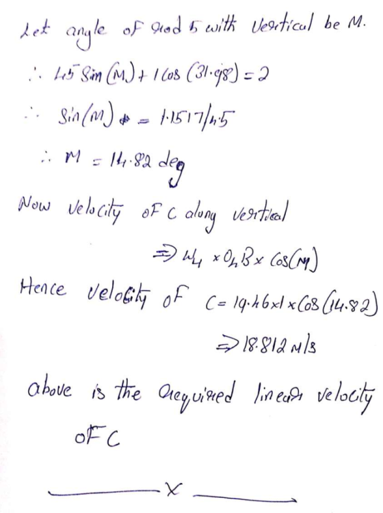
Problem #9: For the mechanism shown in shown, determine the rotational speed of link 4 and the near velocity of point C using complex numbers method. rozA2 3.0 cm: ro4B = 1cm roO 5.0 cm; rBC 4.5 cm 18 rad/s CW (constant) 02= 150° 6 A2 on 2 A4 on 4 -2.0 cm
Problem #9: For the mechanism shown in shown, determine the rotational speed of link 4 and the near velocity of point C using...
kinematic design of machinery
Problem #9: For the mechanism shown in shown, determine the rotational speed of link 4 and the near velocity of point C using complex numbers method. rozA2 3.0 cm: ro4B = 1cm roO 5.0 cm; rBC 4.5 cm 18 rad/s CW (constant) 02= 150° 6 A2 on 2 A4 on 4 -2.0 cm
Problem #9: For the mechanism shown in shown, determine the rotational speed of link 4 and the near velocity of point C using...
Please change the rotational speeds of link 02-A from 120 r/min to 75 r/min and add a rotational speed of N = 100 r/...
 Please change the rotational speeds of link 02-A from
120 r/min to 75 r/min and add a rotational speed of N = 100 r/min
to link 05-D. RESPECTIVILY.
Then find the rotational speed of link 07-B. FROM THE VELOCITY
DIAGRAM.
Thank you.
In the mechanism of figure Q1 crank O-A rotates at 120 rev/min clockwise about rotational speed. Slider B slides on sliding link AC. The are as follows: O2A 6,0 cm, CD 10 cm, AB 2 cm, AC 8...
Please change the rotational speeds of link 02-A from
120 r/min to 75 r/min and add a rotational speed of N = 100 r/min
to link 05-D. RESPECTIVILY.
Then find the rotational speed of link 07-B. FROM THE VELOCITY
DIAGRAM.
Thank you.
In the mechanism of figure Q1 crank O-A rotates at 120 rev/min clockwise about rotational speed. Slider B slides on sliding link AC. The are as follows: O2A 6,0 cm, CD 10 cm, AB 2 cm, AC 8...
Important Note: • It is required to solve each problem in separate sheet. • You are...
 Important Note: • It is required to solve each problem in separate sheet. • You are requested to solve problems 1, 3, and 5 using AutoCAD. Problem (1) In the mechanism shown, link 2 is rotating CW at the constant rate of 4 rad/s. In the position shown, is 53. Determine: vc, 03, 04. Link Lengths: AB = 100 mm, BC = 160 mm, CD = 200 mm 160 mm 220 mm DO Problem (2) In the mechanism shown, link...
Question 1 75 In the mechanism of figure Q1 crank O2A rotates at 120 rev/min clockwise about O2 at a constant rotational speed. Slider B slides on sliding link AC. The dimensions of the links of the...
 Question 1 75 In the mechanism of figure Q1 crank O2A rotates at 120 rev/min clockwise about O2 at a constant rotational speed. Slider B slides on sliding link AC. The dimensions of the links of the mechanism are as follows: O2A 6,0 cm, CD 10 cm, AB 2 cm, AC 8 cm, OsD- 4 cm and OrB 5cm. Angle 02 1100 and 0s- 100. and OsD rototes at toorev/min Construct a velocity diagram for this position and then find...
Question 1 In the mechanism of figure Q1 crank O2A rotates at 70 revim rotational speed. Slider B slides on sliding...
 Question 1 In the mechanism of figure Q1 crank O2A rotates at 70 revim rotational speed. Slider B slides on sliding link AC. T are as follows: O2A 6,0 cm, CD 10 cm, AB 2 cm, AC 8 cm, OsD 4 cm and O Angle θ2-1100 and θ5-100. Rotation) speed for 05 D:looney/ml Construct a velocity diagram for this position and t in clockwise about O2 at a constant he dimensions of the links of the mechanism [101 hen find...
In the mechanism shown, the gear wheel has angular speed 3 rad/s at a certain instant....
 In the mechanism shown, the gear wheel has angular speed 3 rad/s at a certain instant. The 90 cm angular velocity of link OA is 3 rad/s 15 Fixed rack Select one: O a. O rad/s o b. 1.5 rad/s CCW O c. 1.5 rad/s CW O d. 3 rad/s CW
ine given 4) In the figure aside, an in-line slider- crank mechanism is shown. a) Calculate the velocity of the cou...
 ine given 4) In the figure aside, an in-line slider- crank mechanism is shown. a) Calculate the velocity of the coupler point D if crank AB is rotating CW wilth a speed of 2 rad/sec b) Calculate the necessary crank if the velocity of the coupler point is required to be 50 cm/sec, at the given position. speed AB 5am BC-10cm 0 30 degrees
ine given 4) In the figure aside, an in-line slider- crank mechanism is shown. a) Calculate...
ine given 4) In the figure aside, an in-line slider- crank mechanism is shown. a) Calculate the velocity of the coupler point D if crank AB is rotating CW wilth a speed of 2 rad/sec b) Calculate the necessary crank if the velocity of the coupler point is required to be 50 cm/sec, at the given position. speed AB 5am BC-10cm 0 30 degrees
ine given 4) In the figure aside, an in-line slider- crank mechanism is shown. a) Calculate...
Question 2 1 pts TOZA(cm) TAB(cm) 02 (rpm CW) 4.9 6.9 117 Determine the rotational speed...
 Question 2 1 pts TOZA(cm) TAB(cm) 02 (rpm CW) 4.9 6.9 117 Determine the rotational speed (in rpm) of link 3 when link 4 (the slider) is in the limit position (and has O velocity) furthest away from the pivot O2? Provide your answer as a whole number in rpm.
4 In the mechanism shown, the centre of mass of link 3 is at G3, which...
 4 In the mechanism shown, the centre of mass of link 3 is at G3, which is located at the centre of link 3. The mass of link 3 is 0.5 kg. Its moment of inertia about G; is 0.0012 N-s2-m. The weights and moments Of inertia of members 2 and 4 may be neglected. Link 2 is driven at a constant angular velocity of 50 rad/s CW by the torque applied to link 2. The mechanism moves in the...
or the mechanism shown, the crank (member 2) rotates with constant angular velocity o The slider...
 or the mechanism shown, the crank (member 2) rotates with constant angular velocity o The slider (member 3) slides inside a curved slot which has a radius of curvature of R (center of curvature at C4). By using complex number method: (i) Derive expressions for V (velocity of link 4) and A (acceleration of link 4) in terms of o2 and ф. (ii) Compute V and A for the case of R1.6", a-09", ф-35, and 02-10 rad/s CCW.
 kinematic design of machinery
Problem #9: For the mechanism shown in shown, determine the rotational speed of link 4 and the near velocity of point C using complex numbers method. rozA2 3.0 cm: ro4B = 1cm roO 5.0 cm; rBC 4.5 cm 18 rad/s CW (constant) 02= 150° 6 A2 on 2 A4 on 4 -2.0 cm
Problem #9: For the mechanism shown in shown, determine the rotational speed of link 4 and the near velocity of point C using...
kinematic design of machinery
Problem #9: For the mechanism shown in shown, determine the rotational speed of link 4 and the near velocity of point C using complex numbers method. rozA2 3.0 cm: ro4B = 1cm roO 5.0 cm; rBC 4.5 cm 18 rad/s CW (constant) 02= 150° 6 A2 on 2 A4 on 4 -2.0 cm
Problem #9: For the mechanism shown in shown, determine the rotational speed of link 4 and the near velocity of point C using...
 Please change the rotational speeds of link 02-A from
120 r/min to 75 r/min and add a rotational speed of N = 100 r/min
to link 05-D. RESPECTIVILY.
Then find the rotational speed of link 07-B. FROM THE VELOCITY
DIAGRAM.
Thank you.
In the mechanism of figure Q1 crank O-A rotates at 120 rev/min clockwise about rotational speed. Slider B slides on sliding link AC. The are as follows: O2A 6,0 cm, CD 10 cm, AB 2 cm, AC 8...
Please change the rotational speeds of link 02-A from
120 r/min to 75 r/min and add a rotational speed of N = 100 r/min
to link 05-D. RESPECTIVILY.
Then find the rotational speed of link 07-B. FROM THE VELOCITY
DIAGRAM.
Thank you.
In the mechanism of figure Q1 crank O-A rotates at 120 rev/min clockwise about rotational speed. Slider B slides on sliding link AC. The are as follows: O2A 6,0 cm, CD 10 cm, AB 2 cm, AC 8...
 Important Note: • It is required to solve each problem in separate sheet. • You are requested to solve problems 1, 3, and 5 using AutoCAD. Problem (1) In the mechanism shown, link 2 is rotating CW at the constant rate of 4 rad/s. In the position shown, is 53. Determine: vc, 03, 04. Link Lengths: AB = 100 mm, BC = 160 mm, CD = 200 mm 160 mm 220 mm DO Problem (2) In the mechanism shown, link...
 Question 1 75 In the mechanism of figure Q1 crank O2A rotates at 120 rev/min clockwise about O2 at a constant rotational speed. Slider B slides on sliding link AC. The dimensions of the links of the mechanism are as follows: O2A 6,0 cm, CD 10 cm, AB 2 cm, AC 8 cm, OsD- 4 cm and OrB 5cm. Angle 02 1100 and 0s- 100. and OsD rototes at toorev/min Construct a velocity diagram for this position and then find...
 Question 1 In the mechanism of figure Q1 crank O2A rotates at 70 revim rotational speed. Slider B slides on sliding link AC. T are as follows: O2A 6,0 cm, CD 10 cm, AB 2 cm, AC 8 cm, OsD 4 cm and O Angle θ2-1100 and θ5-100. Rotation) speed for 05 D:looney/ml Construct a velocity diagram for this position and t in clockwise about O2 at a constant he dimensions of the links of the mechanism [101 hen find...
 In the mechanism shown, the gear wheel has angular speed 3 rad/s at a certain instant. The 90 cm angular velocity of link OA is 3 rad/s 15 Fixed rack Select one: O a. O rad/s o b. 1.5 rad/s CCW O c. 1.5 rad/s CW O d. 3 rad/s CW
 ine given 4) In the figure aside, an in-line slider- crank mechanism is shown. a) Calculate the velocity of the coupler point D if crank AB is rotating CW wilth a speed of 2 rad/sec b) Calculate the necessary crank if the velocity of the coupler point is required to be 50 cm/sec, at the given position. speed AB 5am BC-10cm 0 30 degrees
ine given 4) In the figure aside, an in-line slider- crank mechanism is shown. a) Calculate...
ine given 4) In the figure aside, an in-line slider- crank mechanism is shown. a) Calculate the velocity of the coupler point D if crank AB is rotating CW wilth a speed of 2 rad/sec b) Calculate the necessary crank if the velocity of the coupler point is required to be 50 cm/sec, at the given position. speed AB 5am BC-10cm 0 30 degrees
ine given 4) In the figure aside, an in-line slider- crank mechanism is shown. a) Calculate...
 Question 2 1 pts TOZA(cm) TAB(cm) 02 (rpm CW) 4.9 6.9 117 Determine the rotational speed (in rpm) of link 3 when link 4 (the slider) is in the limit position (and has O velocity) furthest away from the pivot O2? Provide your answer as a whole number in rpm.
 4 In the mechanism shown, the centre of mass of link 3 is at G3, which is located at the centre of link 3. The mass of link 3 is 0.5 kg. Its moment of inertia about G; is 0.0012 N-s2-m. The weights and moments Of inertia of members 2 and 4 may be neglected. Link 2 is driven at a constant angular velocity of 50 rad/s CW by the torque applied to link 2. The mechanism moves in the...
 or the mechanism shown, the crank (member 2) rotates with constant angular velocity o The slider (member 3) slides inside a curved slot which has a radius of curvature of R (center of curvature at C4). By using complex number method: (i) Derive expressions for V (velocity of link 4) and A (acceleration of link 4) in terms of o2 and ф. (ii) Compute V and A for the case of R1.6", a-09", ф-35, and 02-10 rad/s CCW.
Most questions answered within 3 hours.
-
Suppose we have a binomial experiment in which success is
defined to be a particular quality...
asked 12 minutes ago -
march the type of cellular control with the description: enzyme
induction and the enzyme repression. How...
asked 21 minutes ago -
Brief Exercise 5-09 (Part Level Submission)
The following information relates to Blue Spruce Corp. for the...
asked 21 minutes ago -
An unknown amount of a compound with a molecular mass of 284.04
g/mol is dissolved in...
asked 27 minutes ago -
You are at rest at a stop sign. There is another stop sign that
is 100...
asked 28 minutes ago -
Calculate the equilibrium electrode potential for Fe3+/Fe2+
redox system, if the initial concentration of Fe2+ is...
asked 31 minutes ago -
Describe in detail with graph and diagram how bonding force,
bonding curves and bonding energy at...
asked 48 minutes ago -
Gingerbread cookies become inedible if not eaten quickly enough.
Clarence is trying to determine how many...
asked 44 minutes ago -
A
crane lifts a 200 kg block a height of 10 m in 18 seconds. What...
asked 47 minutes ago -
A 12.0-g bullet is fired horizontally into a 115-g wooden block
that is initially at rest...
asked 47 minutes ago -
Which DNA primer would have the HIGHEST melting temperature?
Question 17 options:
a)
GCATCGGC
b)
AATCGGAT...
asked 55 minutes ago -
what is the charge on the chromium ion in Cr2O3.
a -3
b -2
c 0...
asked 55 minutes ago