
C++20)(0+12 For Questions9 and 10: In Figure 1, Gp(s) and Ge(s)K. Table 1: Table of specific points on Bode Plot for the system given above w(rad/s) - 0.5 5.68 10 20 44.4 -61.6 -66.4 -82.7 -72 -100 mag phase -9.51 -90 -131 -180 -224 9. What is the maximum value of K in the system described above will ensure system stability? (Note that the answers are not in dB) (a) 1.36 x 10⁴ (b 8.13 x 10⁴ ©~ 3.18 x 10⁵ d 7.33 x 10⁵ e None of the above 10. What is wa for the system described above, i.e. what is the frequency at which the maximum value of K is obtained? (a10 rad/s b44.4 rad/s 5.68 rad/s 20 rad/s e None of the above 2
Homework Answers


Add Answer to:
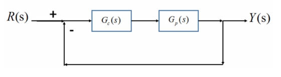
R(s) .Y(s) G,(s) G. (s) C++20)(0+12 For Questions9 and 10: In Figure 1, Gp(s) and Ge(s)K. Table 1: Table of specific po...
R(S) + G(s) G (5) Y(s) Figure 1: For most problems For Questions 4-8: In Figure...
 R(S) + G(s) G (5) Y(s) Figure 1: For most problems For Questions 4-8: In Figure 1, Gp(s) = (s+4)(8+7) (s+5)(8+20) (s+12) and Gc(s) = 80. 4. What is the initial magnitude of the Bode plot for the system described above? (a) 12.48 dB • (b) 5.42 dB (c) 0.27 dB (d) 0.62 dB (e) None of the above 1 5. What is the initial magnitude slope of the Bode plot for the system described abov (a) 20 dB/dec •...
Consider the system given below where K is a constant gain, Gp is the plant, and Ge is a compensator. The Bode Plots of a Gp is given below. Problem 1: Bode Diagram 20 2 40 -60 80 -100 90 135 180 a 2...
 Consider the system given below where K is a constant gain, Gp is the plant, and Ge is a compensator. The Bode Plots of a Gp is given below. Problem 1: Bode Diagram 20 2 40 -60 80 -100 90 135 180 a 225 270 101 10 Frequency (rad/s) 102 a. Looking at the low frequency behavior, determine its number of poles at origin. Explain. b. Looking at the high frequency behavior, determine the number of excess poles. Explain. C....
Y(s) C(s) G(s) R(S) Figure 1: Closed-loop system Q2 Consider the setup in Figure 1 with S s1 (i) ...
 Y(s) C(s) G(s) R(S) Figure 1: Closed-loop system Q2 Consider the setup in Figure 1 with S s1 (i) Design a K,τ, α in the lead compensator 1TOS so that the closed-loop system shown in Figure 1 has a steady state error of.0 for a unit ramp reference input at R and a phase margin of about 45 degrees K, α, τ without Bode plots. When you add phase with the lead compensator add an additional 10 degrees of phase....
Q.4 A position control system is shown in Figure Q4. Assume that K(s) = K, the plant 50 s(0.2s +1) transfer function is given by G(s) s02s y(t) r(t) Figure Q4: Feedback control system. (a) Design a l...
 Q.4 A position control system is shown in Figure Q4. Assume that K(s) = K, the plant 50 s(0.2s +1) transfer function is given by G(s) s02s y(t) r(t) Figure Q4: Feedback control system. (a) Design a lead compensator so that the closed-loop system satisfies the following specifications (i) The steady-state error to a unit-ramp input is less than 1/200 (ii) The unit-step response has an overshoot of less than 16% Ts +1 Hint: Compensator, Dc(s)=aTs+ 1, wm-T (18 marks)...
10 Q.1 Figure Q1 shows a speed control system where Gi(s) 0.5s 1' and K(s)kp K(s) G,(s) Figure Q1: Speed Control System a) Determine the transfer function from d to y (4 marks) (b) Assuming the r...
 10 Q.1 Figure Q1 shows a speed control system where Gi(s) 0.5s 1' and K(s)kp K(s) G,(s) Figure Q1: Speed Control System a) Determine the transfer function from d to y (4 marks) (b) Assuming the reference is zero, what is the steady-state error (e-r - y), in this case, you want yss since r 0) due to an unit step disturbance in d? What must the value of k be in order to make the steady-state error less than...
The parameters are as follows k=0.1,a=1.00,b=1,c=1.0,d=25,w_1=20,w_2=25,Kv=50 e(t) r(t) e (t) G(s) Figure 1: Feedback...
 The parameters are as follows
k=0.1,a=1.00,b=1,c=1.0,d=25,w_1=20,w_2=25,Kv=50
e(t) r(t) e (t) G(s) Figure 1: Feedback control system A pulley and belt transmission has a linearized relationship between the driven pulley angle e (t) in degrees and the input torque u(t) in Newton meters given by the following differential equation du(t) dt A feedback control system (illustrated in Figure 1) needs to be designed such that the closed-loop system is asymptotically stable and such that the following design criteria are met 1....
The parameters are as follows
k=0.1,a=1.00,b=1,c=1.0,d=25,w_1=20,w_2=25,Kv=50
e(t) r(t) e (t) G(s) Figure 1: Feedback control system A pulley and belt transmission has a linearized relationship between the driven pulley angle e (t) in degrees and the input torque u(t) in Newton meters given by the following differential equation du(t) dt A feedback control system (illustrated in Figure 1) needs to be designed such that the closed-loop system is asymptotically stable and such that the following design criteria are met 1....
 R(S) + G(s) G (5) Y(s) Figure 1: For most problems For Questions 4-8: In Figure 1, Gp(s) = (s+4)(8+7) (s+5)(8+20) (s+12) and Gc(s) = 80. 4. What is the initial magnitude of the Bode plot for the system described above? (a) 12.48 dB • (b) 5.42 dB (c) 0.27 dB (d) 0.62 dB (e) None of the above 1 5. What is the initial magnitude slope of the Bode plot for the system described abov (a) 20 dB/dec •...
 Consider the system given below where K is a constant gain, Gp is the plant, and Ge is a compensator. The Bode Plots of a Gp is given below. Problem 1: Bode Diagram 20 2 40 -60 80 -100 90 135 180 a 225 270 101 10 Frequency (rad/s) 102 a. Looking at the low frequency behavior, determine its number of poles at origin. Explain. b. Looking at the high frequency behavior, determine the number of excess poles. Explain. C....
 Y(s) C(s) G(s) R(S) Figure 1: Closed-loop system Q2 Consider the setup in Figure 1 with S s1 (i) Design a K,τ, α in the lead compensator 1TOS so that the closed-loop system shown in Figure 1 has a steady state error of.0 for a unit ramp reference input at R and a phase margin of about 45 degrees K, α, τ without Bode plots. When you add phase with the lead compensator add an additional 10 degrees of phase....
 Q.4 A position control system is shown in Figure Q4. Assume that K(s) = K, the plant 50 s(0.2s +1) transfer function is given by G(s) s02s y(t) r(t) Figure Q4: Feedback control system. (a) Design a lead compensator so that the closed-loop system satisfies the following specifications (i) The steady-state error to a unit-ramp input is less than 1/200 (ii) The unit-step response has an overshoot of less than 16% Ts +1 Hint: Compensator, Dc(s)=aTs+ 1, wm-T (18 marks)...
 10 Q.1 Figure Q1 shows a speed control system where Gi(s) 0.5s 1' and K(s)kp K(s) G,(s) Figure Q1: Speed Control System a) Determine the transfer function from d to y (4 marks) (b) Assuming the reference is zero, what is the steady-state error (e-r - y), in this case, you want yss since r 0) due to an unit step disturbance in d? What must the value of k be in order to make the steady-state error less than...
 The parameters are as follows
k=0.1,a=1.00,b=1,c=1.0,d=25,w_1=20,w_2=25,Kv=50
e(t) r(t) e (t) G(s) Figure 1: Feedback control system A pulley and belt transmission has a linearized relationship between the driven pulley angle e (t) in degrees and the input torque u(t) in Newton meters given by the following differential equation du(t) dt A feedback control system (illustrated in Figure 1) needs to be designed such that the closed-loop system is asymptotically stable and such that the following design criteria are met 1....
The parameters are as follows
k=0.1,a=1.00,b=1,c=1.0,d=25,w_1=20,w_2=25,Kv=50
e(t) r(t) e (t) G(s) Figure 1: Feedback control system A pulley and belt transmission has a linearized relationship between the driven pulley angle e (t) in degrees and the input torque u(t) in Newton meters given by the following differential equation du(t) dt A feedback control system (illustrated in Figure 1) needs to be designed such that the closed-loop system is asymptotically stable and such that the following design criteria are met 1....
Most questions answered within 3 hours.
-
Please help me with FLOWCHART and UML diagram for class,
thank you!
#include <iostream>
#include <fstream>...
asked 39 minutes ago -
3. Describe the “logic circuit” of the Lac operon. Which
proteins are bound or not to...
asked 40 minutes ago -
Ayesha’s adjusted gross income is $60,000 in 2019. She donated a
piece of artwork with a...
asked 47 minutes ago -
For Dijkstra’s shortest path algorithm:
a. Give the Big-O time for Dijkstra’s shortest path algorithm
and...
asked 59 minutes ago -
Phosphorus violates the 'octet rule' in biological molecules,
forming more covalent bonds than expected based on...
asked 1 hour ago -
A 1.3 eV electron has a 10-4 probability of tunneling
through a 2.4 eV potential barrier....
asked 1 hour ago -
What is the one ingredient that is common to being successful
with all stakeholders?
profit
trust...
asked 1 hour ago -
Write an assembly language 32 bit program that reads in lines of
text by a .txt...
asked 1 hour ago -
what is the density ( in g/L) of hydrogen gas at 29 degrees C and a...
asked 1 hour ago -
5-6. You are considering three investment alternatives for some
spare cash: Old Reliable Corporation stock (A1),...
asked 1 hour ago -
Problem 16-02
Receivables Investment
Medwig Corporation has a DSO of 45 days. The company averages
$7,250...
asked 1 hour ago -
Mr. Brown hired Lowe's Maintenance Services Limited to repair
and paint the exterior wall of his...
asked 1 hour ago