In the figure below, let R = 7.00 Ω, L = 2.50 mH, and C =...
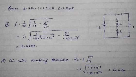
In the figure below, let R = 7.00 Ω, L = 2.50 mH, and C = 1.75 µF.
The circuit is a rectangular loop with a vertical wire in the middle that extends from the bottom side of the loop to almost reach the top side, ending at point b below the top side. The left side contains a battery of emf ℰ with the positive terminal above the negative terminal. The right side contains a capacitor C. The top side, from left to right, contains point a and a switch S in contact with point a. The vertical wire contains, from top to bottom, point b, an inductor L, and a resistor R.
(a) Calculate the frequency of the damped oscillation of the
circuit when the switch is thrown to position b.
kHz
(b) What is the critical resistance for damped oscillations?
Ω
Homework Answers
In the figure below, let R = 7.50 Ω, L = 2.10 mH, and C =...
 In the figure below, let R = 7.50 Ω, L = 2.10 mH, and C = 1.60
µF.
(a) Calculate the frequency of the damped oscillation of the
circuit when the switch is thrown to position b. ? kHz
(b) What is the critical resistance for damped oscillations? ?
Ω
In the figure below, let R = 7.50 Ω, L = 2.10 mH, and C = 1.60
µF.
(a) Calculate the frequency of the damped oscillation of the
circuit when the switch is thrown to position b. ? kHz
(b) What is the critical resistance for damped oscillations? ?
Ω
A 12.0 V battery is connected into a series circuit containing a 20.0 Ω resistor and...
 A 12.0 V battery is connected into a series circuit containing a
20.0 Ω resistor and a 2.70 H inductor.
(a)
In what time interval (in s) will the current reach 50.0% of its
final value?
s
(b)
In what time interval (in s) will the current reach 90.0% of its
final value?
s
What If? After a very long time, using a switch
like that shown in the figure below, the battery is removed and the
inductor is connected...
A 12.0 V battery is connected into a series circuit containing a
20.0 Ω resistor and a 2.70 H inductor.
(a)
In what time interval (in s) will the current reach 50.0% of its
final value?
s
(b)
In what time interval (in s) will the current reach 90.0% of its
final value?
s
What If? After a very long time, using a switch
like that shown in the figure below, the battery is removed and the
inductor is connected...
In the figure below, let R=7.10 Ω, L=2.30 mH, and C=2.00 μF.
 In the figure below, let R=7.10 Ω, L=2.30 mH, and C=2.00 μF.(a) Calculate the frequency of the damped oscillation of the circuit when the switch is thrown to position b.(b) What is the critical resistance for damped oscillations?
13. + -/2 points SerPSET9 32.P057 In the figure below, let R-7.50 Ω, L-2.35 mH, and...
 13. + -/2 points SerPSET9 32.P057 In the figure below, let R-7.50 Ω, L-2.35 mH, and C-1.90 μF. 7 20 o ib (a) Calculate the frequency of the damped oscillation of the circuit when the switch is thrown to position b. kHz (b) What is the critical resistance for damped oscillations? Need Help? Read It
In the circuit of the figure below, the current I1 is 2.4 A and the values...
In the circuit of the figure below, the current I1 is 2.4 A and the values of e m f and R are unknown. What are the currents I2 and I3? (Enter the magnitude only.) I2 = I3 = A circuit is comprised of two adjacent square loops that share a side such that the right side of the left loop is also the left side of the right loop. The two loops meet at point a at the top...
In the circuit of the figure below, the currentI1 is 3.3 A and the values...
 In the circuit of the figure below, the currentI1 is 3.3 A and the values of andR are unknown. What are the currentsI2 and I3? (Enter the
magnitude only.)I2 =I3 =A circuit is comprised of two adjacent square loops that share a
side such that the right side of the left loop is also the left
side of the right loop. The two loops meet at point a at
the top of the shared side and point b at the bottom...
In the circuit of the figure below, the currentI1 is 3.3 A and the values of andR are unknown. What are the currentsI2 and I3? (Enter the
magnitude only.)I2 =I3 =A circuit is comprised of two adjacent square loops that share a
side such that the right side of the left loop is also the left
side of the right loop. The two loops meet at point a at
the top of the shared side and point b at the bottom...
Consider a series RC circuit as in the figure below for which R = 2.40 MΩ,...
 Consider a series RC circuit as in the figure below for
which R = 2.40 MΩ, C = 6.80 μF, and
= 32.0 V.
The circuit is a rectangular loop. The bottom side of the loop
has a battery labeled emf ℰ, oriented with the positive
terminal to the right of the negative terminal. The right side has
a resistor R. The top side contains an open switch S. The
left side has a capacitor C.
(a) Find the time...
Consider a series RC circuit as in the figure below for
which R = 2.40 MΩ, C = 6.80 μF, and
= 32.0 V.
The circuit is a rectangular loop. The bottom side of the loop
has a battery labeled emf ℰ, oriented with the positive
terminal to the right of the negative terminal. The right side has
a resistor R. The top side contains an open switch S. The
left side has a capacitor C.
(a) Find the time...
An LC circuit like the one in the figure below contains an 80.0 mH inductor and...
 An LC circuit like the one in the figure below contains
an 80.0 mH inductor and a 30.0 µF capacitor that initially carries
a 175 µC charge. The switch is open for t < 0 and is
then thrown closed at t = 0.
A rectangular loop forms an L C circuit. The
left side of the loop contains a capacitor C carrying a
charge Qmax, with the positively charged plate
above the negatively charged plate. The right side of...
An LC circuit like the one in the figure below contains
an 80.0 mH inductor and a 30.0 µF capacitor that initially carries
a 175 µC charge. The switch is open for t < 0 and is
then thrown closed at t = 0.
A rectangular loop forms an L C circuit. The
left side of the loop contains a capacitor C carrying a
charge Qmax, with the positively charged plate
above the negatively charged plate. The right side of...
Find the equivalent capacitance of the group of capacitors shown in the figure below. (Let C1...
Find the equivalent capacitance of the group of capacitors shown in the figure below. (Let C1 = 4.60 µF, C2 = 3.80 µF, C3 = 3.10 µF, C4 = 2.20 µF, C5 = 2.70 µF, C6 = 7.20 µF, C7 = 6.10 µF.) A circuit is made up of two rectangular loops, one on top of the other. The bottom side of the lower loop contains a 48.0 V battery, where its positive terminal is to the left of its...
An LC circuit like the one in the figure below contains an 80.0 mH inductor and...
 An LC circuit like the one in the figure below contains
an 80.0 mH inductor and a 30.0 µF capacitor that initially carries
a 175 µC charge. The switch is open for t < 0 and is
then thrown closed at t = 0.
A rectangular loop forms an L C circuit. The
left side of the loop contains a capacitor C carrying a
charge Qmax, with the positively charged plate
above the negatively charged plate. The right side of...
An LC circuit like the one in the figure below contains
an 80.0 mH inductor and a 30.0 µF capacitor that initially carries
a 175 µC charge. The switch is open for t < 0 and is
then thrown closed at t = 0.
A rectangular loop forms an L C circuit. The
left side of the loop contains a capacitor C carrying a
charge Qmax, with the positively charged plate
above the negatively charged plate. The right side of...
 In the figure below, let R = 7.50 Ω, L = 2.10 mH, and C = 1.60
µF.
(a) Calculate the frequency of the damped oscillation of the
circuit when the switch is thrown to position b. ? kHz
(b) What is the critical resistance for damped oscillations? ?
Ω
In the figure below, let R = 7.50 Ω, L = 2.10 mH, and C = 1.60
µF.
(a) Calculate the frequency of the damped oscillation of the
circuit when the switch is thrown to position b. ? kHz
(b) What is the critical resistance for damped oscillations? ?
Ω
 A 12.0 V battery is connected into a series circuit containing a
20.0 Ω resistor and a 2.70 H inductor.
(a)
In what time interval (in s) will the current reach 50.0% of its
final value?
s
(b)
In what time interval (in s) will the current reach 90.0% of its
final value?
s
What If? After a very long time, using a switch
like that shown in the figure below, the battery is removed and the
inductor is connected...
A 12.0 V battery is connected into a series circuit containing a
20.0 Ω resistor and a 2.70 H inductor.
(a)
In what time interval (in s) will the current reach 50.0% of its
final value?
s
(b)
In what time interval (in s) will the current reach 90.0% of its
final value?
s
What If? After a very long time, using a switch
like that shown in the figure below, the battery is removed and the
inductor is connected...
 13. + -/2 points SerPSET9 32.P057 In the figure below, let R-7.50 Ω, L-2.35 mH, and C-1.90 μF. 7 20 o ib (a) Calculate the frequency of the damped oscillation of the circuit when the switch is thrown to position b. kHz (b) What is the critical resistance for damped oscillations? Need Help? Read It
 In the circuit of the figure below, the currentI1 is 3.3 A and the values of andR are unknown. What are the currentsI2 and I3? (Enter the
magnitude only.)I2 =I3 =A circuit is comprised of two adjacent square loops that share a
side such that the right side of the left loop is also the left
side of the right loop. The two loops meet at point a at
the top of the shared side and point b at the bottom...
In the circuit of the figure below, the currentI1 is 3.3 A and the values of andR are unknown. What are the currentsI2 and I3? (Enter the
magnitude only.)I2 =I3 =A circuit is comprised of two adjacent square loops that share a
side such that the right side of the left loop is also the left
side of the right loop. The two loops meet at point a at
the top of the shared side and point b at the bottom...
 Consider a series RC circuit as in the figure below for
which R = 2.40 MΩ, C = 6.80 μF, and
= 32.0 V.
The circuit is a rectangular loop. The bottom side of the loop
has a battery labeled emf ℰ, oriented with the positive
terminal to the right of the negative terminal. The right side has
a resistor R. The top side contains an open switch S. The
left side has a capacitor C.
(a) Find the time...
Consider a series RC circuit as in the figure below for
which R = 2.40 MΩ, C = 6.80 μF, and
= 32.0 V.
The circuit is a rectangular loop. The bottom side of the loop
has a battery labeled emf ℰ, oriented with the positive
terminal to the right of the negative terminal. The right side has
a resistor R. The top side contains an open switch S. The
left side has a capacitor C.
(a) Find the time...
 An LC circuit like the one in the figure below contains
an 80.0 mH inductor and a 30.0 µF capacitor that initially carries
a 175 µC charge. The switch is open for t < 0 and is
then thrown closed at t = 0.
A rectangular loop forms an L C circuit. The
left side of the loop contains a capacitor C carrying a
charge Qmax, with the positively charged plate
above the negatively charged plate. The right side of...
An LC circuit like the one in the figure below contains
an 80.0 mH inductor and a 30.0 µF capacitor that initially carries
a 175 µC charge. The switch is open for t < 0 and is
then thrown closed at t = 0.
A rectangular loop forms an L C circuit. The
left side of the loop contains a capacitor C carrying a
charge Qmax, with the positively charged plate
above the negatively charged plate. The right side of...
Most questions answered within 3 hours.
-
B. If compound Y has approximately the same values of solubility
in toluene as compound X,...
asked 40 minutes ago -
Oscar Inc. has inventory in Japan valued at 39,051,000 Yen one
year ago. One year ago...
asked 47 minutes ago -
If Canada suffered from "fundamental disequilibrium," and its
government choose not to devalue its currency, a...
asked 55 minutes ago -
4. How many input & output Key Value Pairs are passed into,
and emitted out of...
asked 51 minutes ago -
Why would your heart not function well if constructed of
skeletal muscle? What is the particular...
asked 59 minutes ago -
Please respond to this essay question in full essay form for
Chemistry 1102 Organic and Biochemistry:...
asked 59 minutes ago -
Determine the head loss and velocity of flow in a water supply main
of 15.0 cm...
asked 1 hour ago -
A marketing executive who knowingly authorizes a shoddy
defective product to be brought to market is...
asked 1 hour ago -
Write a psudocode:
1. Define a function called authorize that takes in 2 strings,
uName, and...
asked 1 hour ago -
What Hall voltage (in mV) is produced by a 0.180 T field applied
across a 2.60...
asked 1 hour ago -
What mass of ethylene glycol (C2H6O2) must be added to 211.0 g
of water to obtain...
asked 1 hour ago -
Mary's employer has a defined benefits retirement plan, which
pay 3.2% of her last year's salary...
asked 1 hour ago