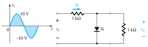
For the network of Fig. 2.171 sketch vo and iR.FIG. 2.171
For the network of Fig. 2.171 sketch vo and iR.
FIG. 2.171
Step-by-Step Solution
Refer to Figure \(2.171\) in the textbook.
The Silicon diode (Si) starts conducting when the output voltage \(v_{o}\) is \(0.7 \mathrm{~V}\).
Calculate the input voltage.
\(v_{o}=\frac{1 \mathrm{k} \Omega v_{i}}{1 \mathrm{k} \Omega+1 \mathrm{k} \Omega}\)
\(0.7 \mathrm{~V}=\frac{1 \mathrm{k} \Omega v_{i}}{1 \mathrm{k} \Omega+1 \mathrm{k} \Omega}\)
\(v_{i}=1.4 \mathrm{~V}\)
When the input voltage \(v_{i} \geq 1.4 \mathrm{~V}\), the Silicon (Si) diode is in ON state and the output voltage \(v_{o}\) is \(0.7 \mathrm{~V}\).
When \(v_{i}<1.4 \mathrm{~V}\), the Silicon (Si) diode is off.
Calculate the level of the output voltage.
$$ \begin{aligned} v_{o} &=\frac{1 \mathrm{k} \Omega}{1 \mathrm{k} \Omega+1 \mathrm{k} \Omega} v_{i} \\ &=0.5 v_{i} \end{aligned} $$
Calculate the output voltage  for an input voltage
  of
of  .
.

Draw the output voltage waveform.

Calculate the voltage across the \(1 \mathrm{k} \Omega\) resistor for positive half cycle.
$$ \begin{aligned} v_{R} &=v_{\max }-0.7 \mathrm{~V} \\ &=10-0.7 \\ &=9.3 \mathrm{~V} \end{aligned} $$
Calculate the current flowing through \(1 \mathrm{k} \Omega\) resistor for positive half cycle.
$$ \begin{aligned} I_{R} &=\frac{v_{R}}{R} \\ &=\frac{9.3 \mathrm{~V}}{1 \mathrm{k} \Omega} \\ &=9.3 \mathrm{~mA} \end{aligned} $$
Calculate the maximum current for the negative peak point  .
.

Draw the waveform for current,  .
.

Most questions answered within 3 hours.
-
Calculating the space time for parallel reactions. m-Xylene is reacted over a ZSM-5 zeolit...
-
Determine Vo and ID for the networks of Fig. 2.160.FIG. 2.160
-
The truck travels along a circular road that has a radius of 50 m at a speed of 4 m/s. F...
-
A state legislature enacted a statute that required any motorcycle operator or passenger...
-
A 1024 × 1024 8-bit image with 5.3 bits/pixel entropy [computed from its histogram using E...
-
In Problem 3.3, we estimated the equationwhere we now report standard errors along with th...
-
In each of the following cases, deduce the nature of the light that is consistent with the...
-
Solve Example 20.5 such that the x, y, z axes move with curvilinear translation, Ω = 0 in...
-
In Fig. 6.43, if i = cos 4t and v = sin 4t, the element is:(a)a resistor(b) a capacitor(c)...
-
Sketch vo for each network of Fig. 2.181 for the input shown.FIG. 2.181
-
(Supplement B) Computing and Reporting Cash Flow Effectsof Sale of Plant and EquipmentDuri...
-
A 350-mL spherical flask contains 0.075 mol of an ideal gas at a temperature of 293 K. Wha...