
Homework Answers

Add Answer to:
Solve the circuit.
m/2 n in Figure Figure 3. (35 points)For the circuit shown in Figure...
please solve them all 2) For the circuit shown in Figure 1. Find the following: A....
 please solve them all
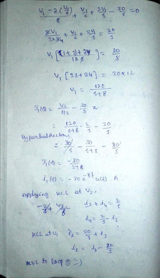
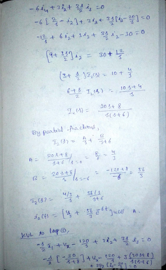
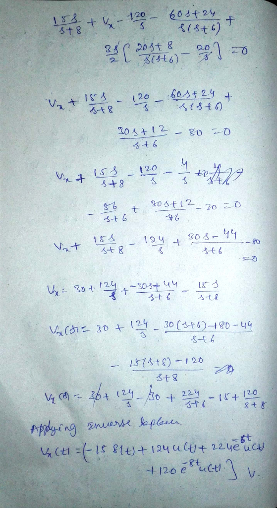
2) For the circuit shown in Figure 1. Find the following: A. How many independent loops are present in the circuit? B. How many nodes are present in the circuit? C. Write a KVL equation at every independent loop (mesh) in the circuit in terms of the indicated voltage and current variables. D. Write a KCL equation at every node in the circuit. Write those equations using the indicated voltage variables by incorporating Ohm's Law for...
please solve them all
2) For the circuit shown in Figure 1. Find the following: A. How many independent loops are present in the circuit? B. How many nodes are present in the circuit? C. Write a KVL equation at every independent loop (mesh) in the circuit in terms of the indicated voltage and current variables. D. Write a KCL equation at every node in the circuit. Write those equations using the indicated voltage variables by incorporating Ohm's Law for...
Please help with number 1. 1 SECTION - A Question 1 - DC Circuits and DC...
 Please help with number 1. 1
SECTION - A Question 1 - DC Circuits and DC Transients [25] After having been open for a very long time, the switch in the circuit shown in Figure 1 is closed at t= 0. Cat Find the currents 11, 12 and is immediately after the switch has been closed. 61 Find the equivalent resistance after the switch is closed and determine the time constant of the circuit. 0 Determine the mathematical expressions for...
Please help with number 1. 1
SECTION - A Question 1 - DC Circuits and DC Transients [25] After having been open for a very long time, the switch in the circuit shown in Figure 1 is closed at t= 0. Cat Find the currents 11, 12 and is immediately after the switch has been closed. 61 Find the equivalent resistance after the switch is closed and determine the time constant of the circuit. 0 Determine the mathematical expressions for...
ON CAPAC Transient RL Circuit Consider the circuit shown in the figure. The resistance of the...
 ON CAPAC Transient RL Circuit Consider the circuit shown in the figure. The resistance of the wire used to make the inductor is negligible compared to the resistors in the circuit. V-140 V, R; -10.Ohms, Ry - 1100 Ohms, and L-200 H RI WWW For this part, assume that switch S has been closed for a long time so that steady currents exist in the circuit. Find (1) the battery current, (2) the current in resistor Ry, and (3) the...
In the circuit shown in Figure-2, the switch was in position-a for a long time. At...
 In the circuit shown in Figure-2, the switch was in position-a for a long time. At time t-0, the switch is moved to position-b. ) Att-0, calculate Vc(+). Q2: 151 1101 Solve Ve () at t20 Find Vc at t 2 sec. switch 25 Figure-2
6: In the circuit shown in Figure-6, input voltage of 15V de was switched ON at t-o. (a) Convert the circuit its Laplace equivalent at t >0, if ILO)-2A and vc (0)-6V. b) Find the capacitor voltage...
 6: In the circuit shown in Figure-6, input voltage of 15V de was switched ON at t-o. (a) Convert the circuit its Laplace equivalent at t >0, if ILO)-2A and vc (0)-6V. b) Find the capacitor voltage, Ve (s) in the frequency domain (c) Solve Ve (t) in the time domain. Switch L= 5H t-o 15V (0 ) = 2A V (o =6V 0.1F
6: In the circuit shown in Figure-6, input voltage of 15V de was switched ON at...
6: In the circuit shown in Figure-6, input voltage of 15V de was switched ON at t-o. (a) Convert the circuit its Laplace equivalent at t >0, if ILO)-2A and vc (0)-6V. b) Find the capacitor voltage, Ve (s) in the frequency domain (c) Solve Ve (t) in the time domain. Switch L= 5H t-o 15V (0 ) = 2A V (o =6V 0.1F
6: In the circuit shown in Figure-6, input voltage of 15V de was switched ON at...
2. (a) Figure 3 shows a circuit where a switch was at Position B for a...
 2. (a) Figure 3 shows a circuit where a switch was at Position B for a long time At time t = 0, the switch was triggered to Position A. Find the initial current 12(0) across the 4 H inductor at time t = 0 Find the time constant ? associated with the circuit when t > 0 Determine the expression of i(t) for t 2 0 given that the circuit is governed by a natural response Find how the...
1. For the circuit shown in figure P-01, determine a. Coupling coefficient of coupled inductors! b. The voltage, Vx as shown in the circuit! C. Energy stored inside the coupled inductors! ML 2Ω Fi...
 1. For the circuit shown in figure P-01, determine a. Coupling coefficient of coupled inductors! b. The voltage, Vx as shown in the circuit! C. Energy stored inside the coupled inductors! ML 2Ω Figure P-01 2. For the ideal transformer circuit shown in figure P-02, determine a. Primary and secondary currents, Ii and I2! b. Primary and secondary voltages, Yi and V2! C. Complex power supplied by the source 1, 2Ω 1:2 6090V ms svo 12Ω Figure P-02
1. For...
1. For the circuit shown in figure P-01, determine a. Coupling coefficient of coupled inductors! b. The voltage, Vx as shown in the circuit! C. Energy stored inside the coupled inductors! ML 2Ω Figure P-01 2. For the ideal transformer circuit shown in figure P-02, determine a. Primary and secondary currents, Ii and I2! b. Primary and secondary voltages, Yi and V2! C. Complex power supplied by the source 1, 2Ω 1:2 6090V ms svo 12Ω Figure P-02
1. For...
Consider the circuit shown in (Figure 1) , where all resistors have the same resistance R....
 Consider the circuit shown in
(Figure
1)
, where all resistors have the same resistance R.
At
t=0,
with the capacitor C
uncharged, the switch is closed.At
t=0,
the three currents can be determined by analyzing a simpler, but
equivalent, circuit. Identify this simpler circuit and use it to
find the values of
I1
,
I2,
and
I3
at
t=0.
Consider the circuit shown in (Figure 1) , where all resistors have the same resistance R. At t=0, with the...
Consider the circuit shown in
(Figure
1)
, where all resistors have the same resistance R.
At
t=0,
with the capacitor C
uncharged, the switch is closed.At
t=0,
the three currents can be determined by analyzing a simpler, but
equivalent, circuit. Identify this simpler circuit and use it to
find the values of
I1
,
I2,
and
I3
at
t=0.
Consider the circuit shown in (Figure 1) , where all resistors have the same resistance R. At t=0, with the...
Question 2: For the circuit shown, the switch was closed for long time, then opened at...
 Question 2: For the circuit shown, the switch was closed for long time, then opened at t-Q. find for all time t a) The current in the inductor i(t) b) The voltage across the inductor vult) 10? t 0 50 i 20 40 V 10?
b) For e circuit shown in Figure 4, the switch S is closed at t =...
 b) For e circuit shown in Figure 4, the switch S is closed at t = 0. the voltage v (t) across the inductor L, given that v(t) = Vsin2nt ft. R = 100 O [6 points) Calculate the voltage v, (t) ac L = 318.3 mH and f = 50 Hz. Figure 4.
 please solve them all
2) For the circuit shown in Figure 1. Find the following: A. How many independent loops are present in the circuit? B. How many nodes are present in the circuit? C. Write a KVL equation at every independent loop (mesh) in the circuit in terms of the indicated voltage and current variables. D. Write a KCL equation at every node in the circuit. Write those equations using the indicated voltage variables by incorporating Ohm's Law for...
please solve them all
2) For the circuit shown in Figure 1. Find the following: A. How many independent loops are present in the circuit? B. How many nodes are present in the circuit? C. Write a KVL equation at every independent loop (mesh) in the circuit in terms of the indicated voltage and current variables. D. Write a KCL equation at every node in the circuit. Write those equations using the indicated voltage variables by incorporating Ohm's Law for...
 Please help with number 1. 1
SECTION - A Question 1 - DC Circuits and DC Transients [25] After having been open for a very long time, the switch in the circuit shown in Figure 1 is closed at t= 0. Cat Find the currents 11, 12 and is immediately after the switch has been closed. 61 Find the equivalent resistance after the switch is closed and determine the time constant of the circuit. 0 Determine the mathematical expressions for...
Please help with number 1. 1
SECTION - A Question 1 - DC Circuits and DC Transients [25] After having been open for a very long time, the switch in the circuit shown in Figure 1 is closed at t= 0. Cat Find the currents 11, 12 and is immediately after the switch has been closed. 61 Find the equivalent resistance after the switch is closed and determine the time constant of the circuit. 0 Determine the mathematical expressions for...
 ON CAPAC Transient RL Circuit Consider the circuit shown in the figure. The resistance of the wire used to make the inductor is negligible compared to the resistors in the circuit. V-140 V, R; -10.Ohms, Ry - 1100 Ohms, and L-200 H RI WWW For this part, assume that switch S has been closed for a long time so that steady currents exist in the circuit. Find (1) the battery current, (2) the current in resistor Ry, and (3) the...
 In the circuit shown in Figure-2, the switch was in position-a for a long time. At time t-0, the switch is moved to position-b. ) Att-0, calculate Vc(+). Q2: 151 1101 Solve Ve () at t20 Find Vc at t 2 sec. switch 25 Figure-2
 6: In the circuit shown in Figure-6, input voltage of 15V de was switched ON at t-o. (a) Convert the circuit its Laplace equivalent at t >0, if ILO)-2A and vc (0)-6V. b) Find the capacitor voltage, Ve (s) in the frequency domain (c) Solve Ve (t) in the time domain. Switch L= 5H t-o 15V (0 ) = 2A V (o =6V 0.1F
6: In the circuit shown in Figure-6, input voltage of 15V de was switched ON at...
6: In the circuit shown in Figure-6, input voltage of 15V de was switched ON at t-o. (a) Convert the circuit its Laplace equivalent at t >0, if ILO)-2A and vc (0)-6V. b) Find the capacitor voltage, Ve (s) in the frequency domain (c) Solve Ve (t) in the time domain. Switch L= 5H t-o 15V (0 ) = 2A V (o =6V 0.1F
6: In the circuit shown in Figure-6, input voltage of 15V de was switched ON at...
 2. (a) Figure 3 shows a circuit where a switch was at Position B for a long time At time t = 0, the switch was triggered to Position A. Find the initial current 12(0) across the 4 H inductor at time t = 0 Find the time constant ? associated with the circuit when t > 0 Determine the expression of i(t) for t 2 0 given that the circuit is governed by a natural response Find how the...
 1. For the circuit shown in figure P-01, determine a. Coupling coefficient of coupled inductors! b. The voltage, Vx as shown in the circuit! C. Energy stored inside the coupled inductors! ML 2Ω Figure P-01 2. For the ideal transformer circuit shown in figure P-02, determine a. Primary and secondary currents, Ii and I2! b. Primary and secondary voltages, Yi and V2! C. Complex power supplied by the source 1, 2Ω 1:2 6090V ms svo 12Ω Figure P-02
1. For...
1. For the circuit shown in figure P-01, determine a. Coupling coefficient of coupled inductors! b. The voltage, Vx as shown in the circuit! C. Energy stored inside the coupled inductors! ML 2Ω Figure P-01 2. For the ideal transformer circuit shown in figure P-02, determine a. Primary and secondary currents, Ii and I2! b. Primary and secondary voltages, Yi and V2! C. Complex power supplied by the source 1, 2Ω 1:2 6090V ms svo 12Ω Figure P-02
1. For...
 Consider the circuit shown in
(Figure
1)
, where all resistors have the same resistance R.
At
t=0,
with the capacitor C
uncharged, the switch is closed.At
t=0,
the three currents can be determined by analyzing a simpler, but
equivalent, circuit. Identify this simpler circuit and use it to
find the values of
I1
,
I2,
and
I3
at
t=0.
Consider the circuit shown in (Figure 1) , where all resistors have the same resistance R. At t=0, with the...
Consider the circuit shown in
(Figure
1)
, where all resistors have the same resistance R.
At
t=0,
with the capacitor C
uncharged, the switch is closed.At
t=0,
the three currents can be determined by analyzing a simpler, but
equivalent, circuit. Identify this simpler circuit and use it to
find the values of
I1
,
I2,
and
I3
at
t=0.
Consider the circuit shown in (Figure 1) , where all resistors have the same resistance R. At t=0, with the...
 Question 2: For the circuit shown, the switch was closed for long time, then opened at t-Q. find for all time t a) The current in the inductor i(t) b) The voltage across the inductor vult) 10? t 0 50 i 20 40 V 10?
 b) For e circuit shown in Figure 4, the switch S is closed at t = 0. the voltage v (t) across the inductor L, given that v(t) = Vsin2nt ft. R = 100 O [6 points) Calculate the voltage v, (t) ac L = 318.3 mH and f = 50 Hz. Figure 4.
Most questions answered within 3 hours.
-
B. If compound Y has approximately the same values of solubility
in toluene as compound X,...
asked 4 minutes ago -
Oscar Inc. has inventory in Japan valued at 39,051,000 Yen one
year ago. One year ago...
asked 11 minutes ago -
4. How many input & output Key Value Pairs are passed into,
and emitted out of...
asked 15 minutes ago -
If Canada suffered from "fundamental disequilibrium," and its
government choose not to devalue its currency, a...
asked 20 minutes ago -
Why would your heart not function well if constructed of
skeletal muscle? What is the particular...
asked 23 minutes ago -
Please respond to this essay question in full essay form for
Chemistry 1102 Organic and Biochemistry:...
asked 24 minutes ago -
Determine the head loss and velocity of flow in a water supply main
of 15.0 cm...
asked 26 minutes ago -
A marketing executive who knowingly authorizes a shoddy
defective product to be brought to market is...
asked 35 minutes ago -
Write a psudocode:
1. Define a function called authorize that takes in 2 strings,
uName, and...
asked 40 minutes ago -
What Hall voltage (in mV) is produced by a 0.180 T field applied
across a 2.60...
asked 39 minutes ago -
What mass of ethylene glycol (C2H6O2) must be added to 211.0 g
of water to obtain...
asked 41 minutes ago -
Mary's employer has a defined benefits retirement plan, which
pay 3.2% of her last year's salary...
asked 44 minutes ago