
Homework Answers


Add Answer to:
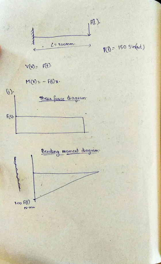
uniim nteverel beom Problem 1: [100 pts The structure below is loaded with the fluctuating force...
Question 1: A rotating shaft with a diameter of 30 mm is made of 1018 cold-rolled...
 Question 1: A rotating shaft with a diameter of 30 mm is made of 1018 cold-rolled steel. The stress concentration factor is 2.366, and the shear stress concentration factor is 1.75 respectively. The notch sensitivity is 0.78 and for shear it's 0.96 Estimate the factor of safety guarding against fatigue failure using modified-Goodman and Soder- berg for each of the following loading conditions: a) The shaft is subjected to a completely reversed torque of 120 N.m in phase with a...
Question 1 1. A steel beam is loaded as shown complete the following a. Draw a...
 Question 1 1. A steel beam is loaded as shown complete the following a. Draw a neat shear force and bending moment diagrams using area moment method b. Determine the maximum bending stress, clearly indication where this occurs c. Determine the maximum shear stress clearly indication where this occurs d, Plot the bending and shear stress for the cross section at x = 5 ft. from the left hand support e. Using area moment method, determine the deflection at the...
Handle structure comprised of 3 round bar elements (AB, BC, CD) as shown in the figure...
 Handle structure comprised of 3 round bar elements (AB, BC, CD) as shown in the figure below. The handle is fixed to the wall at A. A 150 lbf force is applied to the free end at D. The dimensions and cross sections are given in the figure. The handle structure is made from AISI 1020 cold drawn (CD) low carbon steel. a) draw the free body diagrams of rods AB, BC, and CD. b) Find the forces, moments and...
3. A 16-foot-long single overhang steel beam is loaded as shown. Assuming a W8 x 35...
 3. A 16-foot-long single overhang steel beam is loaded as shown. Assuming a W8 x 35 section, determine the maximum bending stress developed. (A992 steel, Fb-30 ksi) (25 points) Gk INSTRUCTIONS For PROBLEM do the following steps: 1. Show ALL your work 2. Draw appropriately labeled FBDs 3. Use appropriate segments to develop expressions for the shear force and bending moment. diagrams in a standard format the required stresses in the critical points in the 4. Draw the shear force...
solve 1 and 3 please Wut unte. 02/06/2020, 12:00pm) Problem 1 (50 pts): For the beam...
 solve 1 and 3 please
Wut unte. 02/06/2020, 12:00pm) Problem 1 (50 pts): For the beam shown, a) Determine the reaction forces at the supports b) Derive the loading, shear-force, and bending moment relationships (g(x), and c) Draw the V(x) and M(x) graphs and identify the locations of the maximum shear force and bending moment along the beam d) Determine the maximum tensile and compressive stresses e) Determine the maximum shear stress due to V 13 kN 50 mm --...
solve 1 and 3 please
Wut unte. 02/06/2020, 12:00pm) Problem 1 (50 pts): For the beam shown, a) Determine the reaction forces at the supports b) Derive the loading, shear-force, and bending moment relationships (g(x), and c) Draw the V(x) and M(x) graphs and identify the locations of the maximum shear force and bending moment along the beam d) Determine the maximum tensile and compressive stresses e) Determine the maximum shear stress due to V 13 kN 50 mm --...
2. (8 points) A solid shaft shown below is loaded in bending and torsion with steady...
 2. (8 points) A solid shaft shown below is loaded in bending and torsion with steady rotation. The total bending moment and torque diagrams are also given. The selected shaft steel material has an ultimate tensile strength Sut = 68kpsi, initial yield stress Sy = 57kpsi, and fully corrected factors for endurance limit, kakykekakek, = 0.60. (a) (6 points) Determine the factor of safety at point D of the shaft using DE-ASME Elliptic criterion. Assume K, = 1.8 and Kfs...
For the Wide-Flange I-beam with distributed load as in figure below calculate: 1) the shear force...
 For the Wide-Flange I-beam with distributed load as in figure below calculate: 1) the shear force V(x) and the bending moment M(x) and plot the shear and bending moment diagrams 2) the maximum bending moment MMAX For the section of the beam with Mwax calculate for each of the points A and B shown in the figure: (a) the flexural stress og (b) the principal stresses 01, 02, 03 c) the principal stress angle Upi (d) the absolute maximum shear...
The structure with a total length of 8 m is loaded by a force F= 8...
 The structure with a total length of 8 m is loaded by a force
F= 8 kN at a distance d= 2.8 m
from the support on the left.
Determine the magnitude of the internal shear force
(positive upward) and the bending moment (counter-clockwise
positive) at a distance x= 1.4 m from the roller support on the
left hand side (express your answer with the appropriate
units).
Vx=
Mx=
---1 -Т.. B N / = positive
The structure with a total length of 8 m is loaded by a force
F= 8 kN at a distance d= 2.8 m
from the support on the left.
Determine the magnitude of the internal shear force
(positive upward) and the bending moment (counter-clockwise
positive) at a distance x= 1.4 m from the roller support on the
left hand side (express your answer with the appropriate
units).
Vx=
Mx=
---1 -Т.. B N / = positive
The cantilever bar in the figure is made from AISI 1018 CD steel and is statically loaded
 The cantilever bar in the figure is made from AISI 1018 CD
steel and is statically loaded with Fy = 800 N, and Fx = Fz = 0.
The fillet radius at the wall is 2 mm with theoretical stress
concentrations of 1.5 for bending, 1.2 for axial, and 2.1 for
torsion.Sut = 440 MPa = 64 kpsi, Sy = 370 MPa = 54 kpsi. Analyze the
stress situation in rod AB by obtaining the following
information.a) Determine the precise...
The cantilever bar in the figure is made from AISI 1018 CD
steel and is statically loaded with Fy = 800 N, and Fx = Fz = 0.
The fillet radius at the wall is 2 mm with theoretical stress
concentrations of 1.5 for bending, 1.2 for axial, and 2.1 for
torsion.Sut = 440 MPa = 64 kpsi, Sy = 370 MPa = 54 kpsi. Analyze the
stress situation in rod AB by obtaining the following
information.a) Determine the precise...
2. Figure 2 below shows a crank loaded by a force F. The material used for...
 2. Figure 2 below shows a crank loaded by a force F. The material used for the crank is steel AISI 4142, and its yield stress is 235 kpsi. Determine the critical load F by using the following different failure theories (assume factor of safety n-2): a. Maximum normal stress theory (MNS); b. Maximum shear stress theory (MSS); c. Distortion-energy theory (DE). Figure 2. A crank under a force F
 Question 1: A rotating shaft with a diameter of 30 mm is made of 1018 cold-rolled steel. The stress concentration factor is 2.366, and the shear stress concentration factor is 1.75 respectively. The notch sensitivity is 0.78 and for shear it's 0.96 Estimate the factor of safety guarding against fatigue failure using modified-Goodman and Soder- berg for each of the following loading conditions: a) The shaft is subjected to a completely reversed torque of 120 N.m in phase with a...
 Question 1 1. A steel beam is loaded as shown complete the following a. Draw a neat shear force and bending moment diagrams using area moment method b. Determine the maximum bending stress, clearly indication where this occurs c. Determine the maximum shear stress clearly indication where this occurs d, Plot the bending and shear stress for the cross section at x = 5 ft. from the left hand support e. Using area moment method, determine the deflection at the...
 Handle structure comprised of 3 round bar elements (AB, BC, CD) as shown in the figure below. The handle is fixed to the wall at A. A 150 lbf force is applied to the free end at D. The dimensions and cross sections are given in the figure. The handle structure is made from AISI 1020 cold drawn (CD) low carbon steel. a) draw the free body diagrams of rods AB, BC, and CD. b) Find the forces, moments and...
 3. A 16-foot-long single overhang steel beam is loaded as shown. Assuming a W8 x 35 section, determine the maximum bending stress developed. (A992 steel, Fb-30 ksi) (25 points) Gk INSTRUCTIONS For PROBLEM do the following steps: 1. Show ALL your work 2. Draw appropriately labeled FBDs 3. Use appropriate segments to develop expressions for the shear force and bending moment. diagrams in a standard format the required stresses in the critical points in the 4. Draw the shear force...
 solve 1 and 3 please
Wut unte. 02/06/2020, 12:00pm) Problem 1 (50 pts): For the beam shown, a) Determine the reaction forces at the supports b) Derive the loading, shear-force, and bending moment relationships (g(x), and c) Draw the V(x) and M(x) graphs and identify the locations of the maximum shear force and bending moment along the beam d) Determine the maximum tensile and compressive stresses e) Determine the maximum shear stress due to V 13 kN 50 mm --...
solve 1 and 3 please
Wut unte. 02/06/2020, 12:00pm) Problem 1 (50 pts): For the beam shown, a) Determine the reaction forces at the supports b) Derive the loading, shear-force, and bending moment relationships (g(x), and c) Draw the V(x) and M(x) graphs and identify the locations of the maximum shear force and bending moment along the beam d) Determine the maximum tensile and compressive stresses e) Determine the maximum shear stress due to V 13 kN 50 mm --...
 2. (8 points) A solid shaft shown below is loaded in bending and torsion with steady rotation. The total bending moment and torque diagrams are also given. The selected shaft steel material has an ultimate tensile strength Sut = 68kpsi, initial yield stress Sy = 57kpsi, and fully corrected factors for endurance limit, kakykekakek, = 0.60. (a) (6 points) Determine the factor of safety at point D of the shaft using DE-ASME Elliptic criterion. Assume K, = 1.8 and Kfs...
 For the Wide-Flange I-beam with distributed load as in figure below calculate: 1) the shear force V(x) and the bending moment M(x) and plot the shear and bending moment diagrams 2) the maximum bending moment MMAX For the section of the beam with Mwax calculate for each of the points A and B shown in the figure: (a) the flexural stress og (b) the principal stresses 01, 02, 03 c) the principal stress angle Upi (d) the absolute maximum shear...
 The structure with a total length of 8 m is loaded by a force
F= 8 kN at a distance d= 2.8 m
from the support on the left.
Determine the magnitude of the internal shear force
(positive upward) and the bending moment (counter-clockwise
positive) at a distance x= 1.4 m from the roller support on the
left hand side (express your answer with the appropriate
units).
Vx=
Mx=
---1 -Т.. B N / = positive
The structure with a total length of 8 m is loaded by a force
F= 8 kN at a distance d= 2.8 m
from the support on the left.
Determine the magnitude of the internal shear force
(positive upward) and the bending moment (counter-clockwise
positive) at a distance x= 1.4 m from the roller support on the
left hand side (express your answer with the appropriate
units).
Vx=
Mx=
---1 -Т.. B N / = positive
 The cantilever bar in the figure is made from AISI 1018 CD
steel and is statically loaded with Fy = 800 N, and Fx = Fz = 0.
The fillet radius at the wall is 2 mm with theoretical stress
concentrations of 1.5 for bending, 1.2 for axial, and 2.1 for
torsion.Sut = 440 MPa = 64 kpsi, Sy = 370 MPa = 54 kpsi. Analyze the
stress situation in rod AB by obtaining the following
information.a) Determine the precise...
The cantilever bar in the figure is made from AISI 1018 CD
steel and is statically loaded with Fy = 800 N, and Fx = Fz = 0.
The fillet radius at the wall is 2 mm with theoretical stress
concentrations of 1.5 for bending, 1.2 for axial, and 2.1 for
torsion.Sut = 440 MPa = 64 kpsi, Sy = 370 MPa = 54 kpsi. Analyze the
stress situation in rod AB by obtaining the following
information.a) Determine the precise...
 2. Figure 2 below shows a crank loaded by a force F. The material used for the crank is steel AISI 4142, and its yield stress is 235 kpsi. Determine the critical load F by using the following different failure theories (assume factor of safety n-2): a. Maximum normal stress theory (MNS); b. Maximum shear stress theory (MSS); c. Distortion-energy theory (DE). Figure 2. A crank under a force F
Most questions answered within 3 hours.
-
Write a java program that declares 10 element array (of type
integers), creates and initializes the...
asked 2 minutes ago -
A $1000 par value convertible bond has a conversion price of
$25. It is currently selling...
asked 5 minutes ago -
import java.util.Arrays;
import java.util.Random;
import java.util.Scanner;
/**
* TODO Write a summary of the role of...
asked 7 minutes ago -
Sodium hydroxide is a strong base and ammonium hydroxide is a
weak base. Which of the...
asked 13 minutes ago -
Glycerol, C3H8O3, is a substance used extensively in the
manufacture of cosmetics, foodstuffs, antifreeze, and plastics....
asked 16 minutes ago -
After moving through Chapter 1 of our textbook, what is a social
issue/area of concern that...
asked 16 minutes ago -
Please complete the implementation of the four functions IN
C.
//************************************************************************************/
//
// countNumberofOnes
//
//...
asked 37 minutes ago -
A memory test consists of 35 tasks. Each task is graded on a
scale of 1...
asked 17 minutes ago -
Construction Cost Analysis and Estimating:
A project requires 17,000 allowed hours. Location of the work is...
asked 26 minutes ago -
1: In 802.11b, Access Point (AP) delivers a nonce to the Station
(STA). This nonce is...
asked 26 minutes ago -
calculate change in entropy and change in enthalpy for freezing
1 mol of water at -10C...
asked 33 minutes ago -
In your opinion, did anyone "win" the Cold War? If no, why? If
yes, who won...
asked 37 minutes ago