

Homework Answers
If the solution is clear, please support with an up-vote. Thank
you and all the very best :)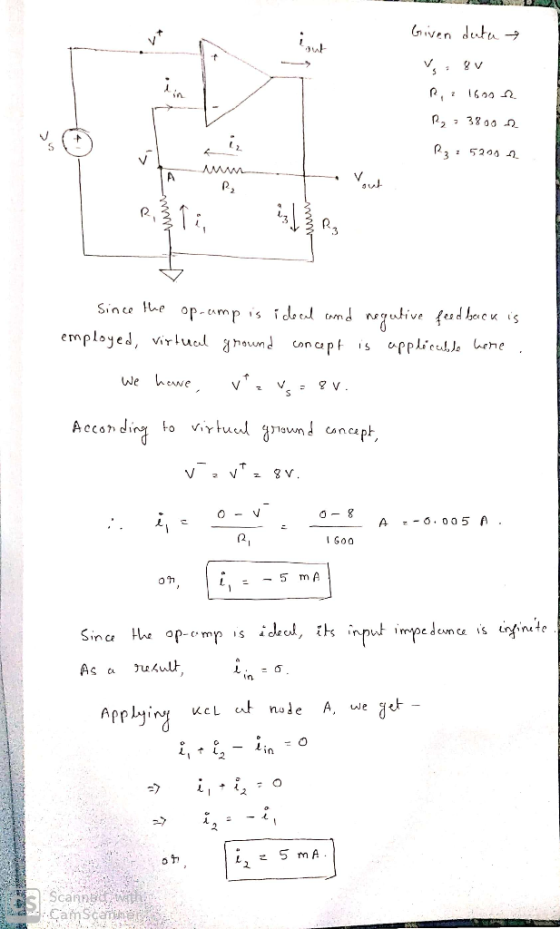

Add Answer to:
NONINVERTING AMPLIFIER
For the circuit below, assume: Vs = 8 Vpp, R1 = 1600 2, R2...
Given V1 = 1 Vpp, V2 = 4 Vpp, Vout = 0.82 Vpp and Rf =...
 Given V1 = 1 Vpp, V2 = 4 Vpp, Vout = 0.82 Vpp and Rf = 2 kq and that R1, R2 and R3 are all equal, find the value of R1 Input resistor R1 = R2 = R3 = ko. (Round your answer to 2 decimal places) RF Vout OA1 R1 Sm R2 + TL081 L 1 : v2 3 R3 Use phasor techniques to determine the current supplied by the source given that V = 12 <0° v,...
Q3. In the circuit as shown below, given that R1 = 4 Ω, R2-4 Ω, L...
 Q3. In the circuit as shown below, given that R1 = 4 Ω, R2-4 Ω, L 2 H, and C = 0.5 F, where vs(t) is given by the waveform displayed in the same figure 1 V (a) Determine the s-domain current I(so) at so-0.05 jo.07 (rad/s): IL(So)- Submit Answer Tries 0/3 (b) Determine the t-domain current i(to) at to 4.5 (s): Submit Answer Tries 0/8 Q4. Determine the output voltage in the circuit as shown below, given that Vs-35*u(t)...
Determine the current through R3=50Ω in the circuit shown in (Figure 1), where vs=60V, R1=30Ω, R2=30Ω,...
 Determine the current through R3=50Ω in the circuit shown in
(Figure 1), where vs=60V, R1=30Ω, R2=30Ω, and R4=60Ω. Express your
answer in amperes to three significant figures.
I need both parts A and B please
▼ Part B Determine the current through R3-50 Ω in the circuit shown in Figure 1), where us Rs 60 S2 Express your answer in amperes to three significant figures. Review 60 V. R-30 Ω. R2 30 Ω, and Learning Goal: To determine the voltage,...
Determine the current through R3=50Ω in the circuit shown in
(Figure 1), where vs=60V, R1=30Ω, R2=30Ω, and R4=60Ω. Express your
answer in amperes to three significant figures.
I need both parts A and B please
▼ Part B Determine the current through R3-50 Ω in the circuit shown in Figure 1), where us Rs 60 S2 Express your answer in amperes to three significant figures. Review 60 V. R-30 Ω. R2 30 Ω, and Learning Goal: To determine the voltage,...
For the driven-right-leg system below along with its equivalent circuit, assume 4. R,-5M0(non-ideal input impedance of op-amp) db Rx Auxiliary op amp RL db R1 Vcm_ Vi R5 2 RF R4 Rx o v RG 0 7 RA Aux...
 For the driven-right-leg system below along with its equivalent circuit, assume 4. R,-5M0(non-ideal input impedance of op-amp) db Rx Auxiliary op amp RL db R1 Vcm_ Vi R5 2 RF R4 Rx o v RG 0 7 RA Auxiliary Amplifier O VREF 2 R2 What are the benefits of using the driven-right-leg circuit? What is the value of the common-mode voltage if resistor RRL is tied to ground instead of the auxiliary amplifier? e.
For the driven-right-leg system below along...
For the driven-right-leg system below along with its equivalent circuit, assume 4. R,-5M0(non-ideal input impedance of op-amp) db Rx Auxiliary op amp RL db R1 Vcm_ Vi R5 2 RF R4 Rx o v RG 0 7 RA Auxiliary Amplifier O VREF 2 R2 What are the benefits of using the driven-right-leg circuit? What is the value of the common-mode voltage if resistor RRL is tied to ground instead of the auxiliary amplifier? e.
For the driven-right-leg system below along...
please solve these 2 problems. I will rate you up In the circuit shown below, let...
 please solve these 2 problems. I will rate you up
In the circuit shown below, let V. - 3 V.1. - 1 mA, R-3k, Ry - 2.5 kA, R = 1 kq Use mesh analysis to find mesh currents I, and 12. Also, find Vı. R1 V1 R2 W 2 is len 3kR 12 R3 100 IMA Problem 5 In the circuit shown below, let V, -8 V, 1. - 2 mA, R2 = 1 k 2, R2 = 400,...
please solve these 2 problems. I will rate you up
In the circuit shown below, let V. - 3 V.1. - 1 mA, R-3k, Ry - 2.5 kA, R = 1 kq Use mesh analysis to find mesh currents I, and 12. Also, find Vı. R1 V1 R2 W 2 is len 3kR 12 R3 100 IMA Problem 5 In the circuit shown below, let V, -8 V, 1. - 2 mA, R2 = 1 k 2, R2 = 400,...
Laboratory 1: operation amplifier characteristics A. Objectives: 1. To study the basic characteri...
 thanks
Laboratory 1: operation amplifier characteristics A. Objectives: 1. To study the basic characteristics of an operational amplifier 2. To study the bias circuit of an operational amplifier B. Apparatus: 1. DC Power supply 2. Experimental board and corresponding components 3. Electronic calculator (prepared by students) 4. Digital camera (prepared by students for photo taking of the experimental results) 5. Laptop computer with the software PicoScope 6 and Microsoft Word installed. 6. PicoScope PC Oscilloscope and its accessories. 7. Multimeter...
thanks
Laboratory 1: operation amplifier characteristics A. Objectives: 1. To study the basic characteristics of an operational amplifier 2. To study the bias circuit of an operational amplifier B. Apparatus: 1. DC Power supply 2. Experimental board and corresponding components 3. Electronic calculator (prepared by students) 4. Digital camera (prepared by students for photo taking of the experimental results) 5. Laptop computer with the software PicoScope 6 and Microsoft Word installed. 6. PicoScope PC Oscilloscope and its accessories. 7. Multimeter...
Voltage and Current Division For the circuit shown, calculate V. V and Vs when V. =...
 Voltage and Current Division For the circuit shown, calculate V. V and Vs when V. = 7 V, R; = 18 2. R2 = 66 2. R3 = 57 2. R4 = 37 and Rs = 332 Express your answer to two significant figures, with appropriate units View Available Hint(s) @? R-180 R2 = 660 + V + 12 0.597 V = 7 V R3 - 570 V 1.89 V R$ = 33 R = 37 Vs + - V4...
An analogue amplifier circuit is shown in Figure 1 below. VDD Q5 15V JL - Vout...
 An analogue amplifier circuit is shown in Figure 1 below. VDD Q5 15V JL - Vout Irer RI Vina JET T7T Figure 1 Integrated amplifier circuit. Circuit Data: Vpp = 15 V, IREF = I1 = I2 = 1.0 mA Transistor Data: Q1: NMOS, un Cox = 80 A/V?, W/L = 100 um/0.8 um, Vtn = 0.8 V, L = 0.10 um/V Q2: NPN BJT, B = 100, Vbe = 0.7 V, VA = 150 V Q3, Q4: NMOS, un...
simple inverting op-amp pspice question. Hello! I am trying to run the below given circuit and...
 simple inverting op-amp pspice question.
Hello! I am trying to run the below given circuit and I am
getting below error
Can you tell me what did I do wrong and what I need to do to fix
this?
[given]
[simulation error]
200 ΚΩ 20 ΚΩ KCL Kcla OVO 1 CHEMATIC1-simy wym MAROLO 11 ) - D O 0ag 5 · X Ø È 市回 Us Map @ Amer SCHEMATIC1-sim 羅 Start Page task13 1 PAGE1* SCHEMATI..-3 PAGE2" R2 VIN...
simple inverting op-amp pspice question.
Hello! I am trying to run the below given circuit and I am
getting below error
Can you tell me what did I do wrong and what I need to do to fix
this?
[given]
[simulation error]
200 ΚΩ 20 ΚΩ KCL Kcla OVO 1 CHEMATIC1-simy wym MAROLO 11 ) - D O 0ag 5 · X Ø È 市回 Us Map @ Amer SCHEMATIC1-sim 羅 Start Page task13 1 PAGE1* SCHEMATI..-3 PAGE2" R2 VIN...
Part e please For the circuit as shown below, given that R1-4Q,R2-2a,R3-10Q,Rs.12Ω. L-4H,C-0.64 F, and VS-18V....
 Part e please
For the circuit as shown below, given that R1-4Q,R2-2a,R3-10Q,Rs.12Ω. L-4H,C-0.64 F, and VS-18V. Ri ic R: 巧 叱: (a) Determine vc(0) and lc(O): vc(0) 5.143 (V); Ic(O) 0.000 (A) You are correct. Previous Thes receipt no. is 163-9387 (b) Determine vc(oo) 0.000 (V) ou are correct. Your receipt no. is 163-5720 (c) Determine the damping coefficient o 0.500 (Np/s) You are correct. receipt no. is 163-348 Previous Tries (d) Determine the resonant frequency 40: 0.625 (rad/s) You...
Part e please
For the circuit as shown below, given that R1-4Q,R2-2a,R3-10Q,Rs.12Ω. L-4H,C-0.64 F, and VS-18V. Ri ic R: 巧 叱: (a) Determine vc(0) and lc(O): vc(0) 5.143 (V); Ic(O) 0.000 (A) You are correct. Previous Thes receipt no. is 163-9387 (b) Determine vc(oo) 0.000 (V) ou are correct. Your receipt no. is 163-5720 (c) Determine the damping coefficient o 0.500 (Np/s) You are correct. receipt no. is 163-348 Previous Tries (d) Determine the resonant frequency 40: 0.625 (rad/s) You...
 Given V1 = 1 Vpp, V2 = 4 Vpp, Vout = 0.82 Vpp and Rf = 2 kq and that R1, R2 and R3 are all equal, find the value of R1 Input resistor R1 = R2 = R3 = ko. (Round your answer to 2 decimal places) RF Vout OA1 R1 Sm R2 + TL081 L 1 : v2 3 R3 Use phasor techniques to determine the current supplied by the source given that V = 12 <0° v,...
 Q3. In the circuit as shown below, given that R1 = 4 Ω, R2-4 Ω, L 2 H, and C = 0.5 F, where vs(t) is given by the waveform displayed in the same figure 1 V (a) Determine the s-domain current I(so) at so-0.05 jo.07 (rad/s): IL(So)- Submit Answer Tries 0/3 (b) Determine the t-domain current i(to) at to 4.5 (s): Submit Answer Tries 0/8 Q4. Determine the output voltage in the circuit as shown below, given that Vs-35*u(t)...
 Determine the current through R3=50Ω in the circuit shown in
(Figure 1), where vs=60V, R1=30Ω, R2=30Ω, and R4=60Ω. Express your
answer in amperes to three significant figures.
I need both parts A and B please
▼ Part B Determine the current through R3-50 Ω in the circuit shown in Figure 1), where us Rs 60 S2 Express your answer in amperes to three significant figures. Review 60 V. R-30 Ω. R2 30 Ω, and Learning Goal: To determine the voltage,...
Determine the current through R3=50Ω in the circuit shown in
(Figure 1), where vs=60V, R1=30Ω, R2=30Ω, and R4=60Ω. Express your
answer in amperes to three significant figures.
I need both parts A and B please
▼ Part B Determine the current through R3-50 Ω in the circuit shown in Figure 1), where us Rs 60 S2 Express your answer in amperes to three significant figures. Review 60 V. R-30 Ω. R2 30 Ω, and Learning Goal: To determine the voltage,...
 For the driven-right-leg system below along with its equivalent circuit, assume 4. R,-5M0(non-ideal input impedance of op-amp) db Rx Auxiliary op amp RL db R1 Vcm_ Vi R5 2 RF R4 Rx o v RG 0 7 RA Auxiliary Amplifier O VREF 2 R2 What are the benefits of using the driven-right-leg circuit? What is the value of the common-mode voltage if resistor RRL is tied to ground instead of the auxiliary amplifier? e.
For the driven-right-leg system below along...
For the driven-right-leg system below along with its equivalent circuit, assume 4. R,-5M0(non-ideal input impedance of op-amp) db Rx Auxiliary op amp RL db R1 Vcm_ Vi R5 2 RF R4 Rx o v RG 0 7 RA Auxiliary Amplifier O VREF 2 R2 What are the benefits of using the driven-right-leg circuit? What is the value of the common-mode voltage if resistor RRL is tied to ground instead of the auxiliary amplifier? e.
For the driven-right-leg system below along...
 please solve these 2 problems. I will rate you up
In the circuit shown below, let V. - 3 V.1. - 1 mA, R-3k, Ry - 2.5 kA, R = 1 kq Use mesh analysis to find mesh currents I, and 12. Also, find Vı. R1 V1 R2 W 2 is len 3kR 12 R3 100 IMA Problem 5 In the circuit shown below, let V, -8 V, 1. - 2 mA, R2 = 1 k 2, R2 = 400,...
please solve these 2 problems. I will rate you up
In the circuit shown below, let V. - 3 V.1. - 1 mA, R-3k, Ry - 2.5 kA, R = 1 kq Use mesh analysis to find mesh currents I, and 12. Also, find Vı. R1 V1 R2 W 2 is len 3kR 12 R3 100 IMA Problem 5 In the circuit shown below, let V, -8 V, 1. - 2 mA, R2 = 1 k 2, R2 = 400,...
 thanks
Laboratory 1: operation amplifier characteristics A. Objectives: 1. To study the basic characteristics of an operational amplifier 2. To study the bias circuit of an operational amplifier B. Apparatus: 1. DC Power supply 2. Experimental board and corresponding components 3. Electronic calculator (prepared by students) 4. Digital camera (prepared by students for photo taking of the experimental results) 5. Laptop computer with the software PicoScope 6 and Microsoft Word installed. 6. PicoScope PC Oscilloscope and its accessories. 7. Multimeter...
thanks
Laboratory 1: operation amplifier characteristics A. Objectives: 1. To study the basic characteristics of an operational amplifier 2. To study the bias circuit of an operational amplifier B. Apparatus: 1. DC Power supply 2. Experimental board and corresponding components 3. Electronic calculator (prepared by students) 4. Digital camera (prepared by students for photo taking of the experimental results) 5. Laptop computer with the software PicoScope 6 and Microsoft Word installed. 6. PicoScope PC Oscilloscope and its accessories. 7. Multimeter...
 Voltage and Current Division For the circuit shown, calculate V. V and Vs when V. = 7 V, R; = 18 2. R2 = 66 2. R3 = 57 2. R4 = 37 and Rs = 332 Express your answer to two significant figures, with appropriate units View Available Hint(s) @? R-180 R2 = 660 + V + 12 0.597 V = 7 V R3 - 570 V 1.89 V R$ = 33 R = 37 Vs + - V4...
 An analogue amplifier circuit is shown in Figure 1 below. VDD Q5 15V JL - Vout Irer RI Vina JET T7T Figure 1 Integrated amplifier circuit. Circuit Data: Vpp = 15 V, IREF = I1 = I2 = 1.0 mA Transistor Data: Q1: NMOS, un Cox = 80 A/V?, W/L = 100 um/0.8 um, Vtn = 0.8 V, L = 0.10 um/V Q2: NPN BJT, B = 100, Vbe = 0.7 V, VA = 150 V Q3, Q4: NMOS, un...
 simple inverting op-amp pspice question.
Hello! I am trying to run the below given circuit and I am
getting below error
Can you tell me what did I do wrong and what I need to do to fix
this?
[given]
[simulation error]
200 ΚΩ 20 ΚΩ KCL Kcla OVO 1 CHEMATIC1-simy wym MAROLO 11 ) - D O 0ag 5 · X Ø È 市回 Us Map @ Amer SCHEMATIC1-sim 羅 Start Page task13 1 PAGE1* SCHEMATI..-3 PAGE2" R2 VIN...
simple inverting op-amp pspice question.
Hello! I am trying to run the below given circuit and I am
getting below error
Can you tell me what did I do wrong and what I need to do to fix
this?
[given]
[simulation error]
200 ΚΩ 20 ΚΩ KCL Kcla OVO 1 CHEMATIC1-simy wym MAROLO 11 ) - D O 0ag 5 · X Ø È 市回 Us Map @ Amer SCHEMATIC1-sim 羅 Start Page task13 1 PAGE1* SCHEMATI..-3 PAGE2" R2 VIN...
 Part e please
For the circuit as shown below, given that R1-4Q,R2-2a,R3-10Q,Rs.12Ω. L-4H,C-0.64 F, and VS-18V. Ri ic R: 巧 叱: (a) Determine vc(0) and lc(O): vc(0) 5.143 (V); Ic(O) 0.000 (A) You are correct. Previous Thes receipt no. is 163-9387 (b) Determine vc(oo) 0.000 (V) ou are correct. Your receipt no. is 163-5720 (c) Determine the damping coefficient o 0.500 (Np/s) You are correct. receipt no. is 163-348 Previous Tries (d) Determine the resonant frequency 40: 0.625 (rad/s) You...
Part e please
For the circuit as shown below, given that R1-4Q,R2-2a,R3-10Q,Rs.12Ω. L-4H,C-0.64 F, and VS-18V. Ri ic R: 巧 叱: (a) Determine vc(0) and lc(O): vc(0) 5.143 (V); Ic(O) 0.000 (A) You are correct. Previous Thes receipt no. is 163-9387 (b) Determine vc(oo) 0.000 (V) ou are correct. Your receipt no. is 163-5720 (c) Determine the damping coefficient o 0.500 (Np/s) You are correct. receipt no. is 163-348 Previous Tries (d) Determine the resonant frequency 40: 0.625 (rad/s) You...
Most questions answered within 3 hours.
-
51.
As the marginal propensity to expend rises, the multiplier:
decreases.
is impossible to determine.
increases....
asked 58 seconds from now -
The Baldwin Company currently has the following balances on their
balance sheet:
Total
Liabilities
$69,309
Common...
asked 2 minutes ago -
A quiet town in Kansas has 10 people, all of whom have the same
preferences. There...
asked 7 minutes ago -
Summarize what an organization needs from a leader.
a. Analyze what might happen to an organization...
asked 10 minutes ago -
How would one critically evaluate an organizations marketing
strategies from the viewpoint of its consumers, as...
asked 9 minutes ago -
Given a standardized normal distribution (with μ = 0 and a σ =
1), what is...
asked 9 minutes ago -
Company XYZ know that replacement times for the quartz time
pieces it produces are normally distributed...
asked 24 minutes ago -
A) Write the acid-base reaction that occurs between Na2HPO4 and
NaOH
B) Write the possible reactions...
asked 38 minutes ago -
What advantages does the Natural Law Theory have in comparison
with the Divine Command Theory? Explain...
asked 44 minutes ago -
A diver comes off a board with arms straight up and legs
straight down, giving her...
asked 43 minutes ago -
Answer the following questions
In your own words, define each of these terms
- Branding, Packaging,...
asked 40 minutes ago -
Briefly discuss developments in the crude oil market and your
outlook, using the microeconomic concepts discussed...
asked 42 minutes ago