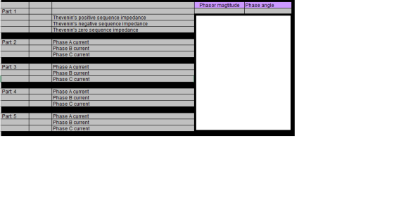
Please help me to answer those question and answer with PHASOR MAGNITUDE and PHASE ANGLE
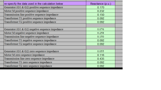
Part 1:
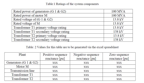
Taking the rated power of generator G1 as the base power, and
the transformer T1 low-voltage
side rated voltage as the base voltage, calculate the Thevanin’s
equivalent zero-sequence
impedance, positive sequence impedance and the negative sequence
impedance viewed from
Bus-2. Specify your answers in per-unit.
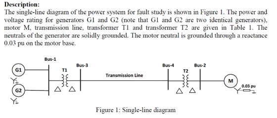
Part 2:
Assuming the pre-fault bus voltages are at 1.02 pu, calculate the
fault currents in each phase for a
three-phase balanced fault at Bus-2. Specify your answers in
per-unit.
Part 3:
Assuming the pre-fault bus voltages are at 1.02 pu, calculate the
fault currents in each phase for a
single-line to ground fault at Bus-2. Specify your answers in
per-unit.
EEET2202 - Assignment-2 2018 page 3 of 3
Part 4:
Assuming the pre-fault bus voltages are at 1.02 pu, calculate the
fault currents in each phase for a line-to-line fault at Bus-2.
Specify your answers in per-unit
.
Part 5:
Assuming the pre-fault bus voltages are at 1.02 pu, calculate the
fault currents in each phase for a line-to-line-to-ground fault at
Bus-2. Specify your answers in per-unit.
Please help me to answer those question and answer with PHASOR MAGNITUDE and PHASE ANGLE
Homework Answers


Add Answer to:
Please help me to answer those question and answer with PHASOR
MAGNITUDE and PHASE ANGLE
Part...
Bus A Bus B R1 TI ine 1 20% 80% line 2 T2 R2 110 kV 11 kV The fault is located at point F, which ...
 Bus A Bus B R1 TI ine 1 20% 80% line 2 T2 R2 110 kV 11 kV The fault is located at point F, which is 20% of the total line 2 length from Bus B Fault MVA 1524.20471 Three-phase fault level in MVA at bus A SPFL (kA) 8 MVA1 MVA2 X1 (96 X2 (96) R1 (2) R2 (Q) z' (Q) Zo (2) Rf (Q) Single phase to ground fault level (kA) at bus A Transformer 1 MVA...
The component parameters for the power system shown in Figure 2 are given in Table 1. The pre-fau...
 The component parameters for the power system shown in Figure 2 are given in Table 1. The pre-fault voltage is 120° pu and Zx-j0.1 pu. Table 1 Ratings X2-Xi (pu)Xo (pu) 0.05 0.10 0.20 0.20 Components G1, G2 200 MVA, 20 kV 0.10 0.10 0.10 0.10 T1, T2, T3200 MVA, 20/200 kV L1 200 MVA, 200 kV し2 200 MVA, 20 kV (a) Draw the three sequence networks and determine the per-unit Thevenin impedance of each sequence network seen from...
BUS 1 BUS 2 LINE 1 T1 L1 T2 G1 G2 R = 0,6 pu LINE 2 L2 T3 G3 BUS 3 a) For the above network, draw positive, negative an...
 BUS 1 BUS 2 LINE 1 T1 L1 T2 G1 G2 R = 0,6 pu LINE 2 L2 T3 G3 BUS 3 a) For the above network, draw positive, negative and zero sequence networks (60 marks) b) Provide the main mathematical steps that will allow you to calculate the magnitude (in ampere) of the phase to phase fault current at BUS 1. As part of your answer you should show clearly, on a diagram, how the networks of part (a)...
can you calculating this question and explain why? thanks The ratings and sequence reactances of the components for...
 can you calculating this question and explain why?
thanks
The ratings and sequence reactances of the components for the power system shown in Figure 2 are given in Table 1. The pre-fault voltage is 1/0° per unit (pu). Bus 8 L3 Bus 1 T1 Bus 4 T2 Bus 2 Bus 5 L1 L2 G1 Bus 3 T3 Bus 7 Bus 6 D.6975 Figure Draw the per unit impedance sequence networks and determine the per unit (a) Thevenin impedances of the...
can you calculating this question and explain why?
thanks
The ratings and sequence reactances of the components for the power system shown in Figure 2 are given in Table 1. The pre-fault voltage is 1/0° per unit (pu). Bus 8 L3 Bus 1 T1 Bus 4 T2 Bus 2 Bus 5 L1 L2 G1 Bus 3 T3 Bus 7 Bus 6 D.6975 Figure Draw the per unit impedance sequence networks and determine the per unit (a) Thevenin impedances of the...
A single line diagram of a power system is shown in Fig. 2. The system data with equipment ratings and assumed sequence reactances are given the following table. The neutrals of the generator and A-Y...
 A single line diagram of a power system is shown in Fig. 2. The system data with equipment ratings and assumed sequence reactances are given the following table. The neutrals of the generator and A-Y transformers are solidly grounded. The motor neutral is grounded through a reactance Xn 0.05 per unit on the motor base. Assume that Pre-fault voltage is takin as VF-1.0 ,0° per unit and Pre- fault load current and Δ-Y transformer phase shift are neglected In the...
Bus A Bus B R1 T1 line 1 20% 80% line 2 T2 R2 110 kV 11 kV The fault is located at point F, which...
 Bus A Bus B R1 T1 line 1 20% 80% line 2 T2 R2 110 kV 11 kV The fault is located at point F, which is 20% of the total line 2 length from Bus B Fault MVA 1524.20471 Three-phase fault level in MVA at bus A SPFL (kA) 8 MVA1 MVA2 X1 (96) X2 (96) R1 (2) R2 (Q) z' (Q) Zo (2) Rf (Q) Single phase to ground fault level (kA) at bus A Transformer 1 MVA...
No calculations needed, just use written labels given. BUS 1 BUS 2 LINE 1 T1 L1 T2. G1 G2 R= 0.6 pu LINE 2 L2 T3 G3 BUS...
 No calculations needed, just use written labels given.
BUS 1 BUS 2 LINE 1 T1 L1 T2. G1 G2 R= 0.6 pu LINE 2 L2 T3 G3 BUS 3 a) For the above network, draw positive, negative and zero sequence networks (40 marks) b) Provide the main mathematical steps that will allow you to calculate the magnitude (in ampere) of the phase to ground fault at the midpoint of line 1 As part of your answer you should show clearly,...
No calculations needed, just use written labels given.
BUS 1 BUS 2 LINE 1 T1 L1 T2. G1 G2 R= 0.6 pu LINE 2 L2 T3 G3 BUS 3 a) For the above network, draw positive, negative and zero sequence networks (40 marks) b) Provide the main mathematical steps that will allow you to calculate the magnitude (in ampere) of the phase to ground fault at the midpoint of line 1 As part of your answer you should show clearly,...
a five bus system
 The equipment ratings for a five bus system are given as Generator G1: 50 MVA, 12 kV, Xd
’’=X2=0.20, X0= 0.10 per unit Generator G2: 100 MVA, 15 kV, Xd
’’=0.2, X2=0.23, X0= 0.10 per unit Transformer T1: 50 MVA, 10 kV (Y)/138 kV (Y), X=0.10 per unit Transformer T1: 100 MVA, 15 kV (∆)/138 kV (Y), X=0.10 per unit Each 138 kV line: X1=40 Ohms, X0=100 ohms (1) Draw out the zero-, positive-, and negative- sequence reactance diagrams for the original system
using a 100-MVA,...
The equipment ratings for a five bus system are given as Generator G1: 50 MVA, 12 kV, Xd
’’=X2=0.20, X0= 0.10 per unit Generator G2: 100 MVA, 15 kV, Xd
’’=0.2, X2=0.23, X0= 0.10 per unit Transformer T1: 50 MVA, 10 kV (Y)/138 kV (Y), X=0.10 per unit Transformer T1: 100 MVA, 15 kV (∆)/138 kV (Y), X=0.10 per unit Each 138 kV line: X1=40 Ohms, X0=100 ohms (1) Draw out the zero-, positive-, and negative- sequence reactance diagrams for the original system
using a 100-MVA,...
For the network shown below, the pu reactance data are equivalent sequence circuit and calculate the fault current in p...
 For the network shown below, the pu reactance data are equivalent sequence circuit and calculate the fault current in per unit for a bolted single line- to-ground fault at bus 2. The pre-fault bus voltages are assumed to be 1 pu given in the table. Draw the Ti T2 1 2 3 G1 G2 5 X2 Item G1 0.10 0.10 0.05 0.05 G2 0.10 0.10 0.01 T1 0.01 0.01 0.01 T2 0.01 0.01 Line 2-3 0.10 0.10 0.20 Line 3-5...
 Bus A Bus B R1 TI ine 1 20% 80% line 2 T2 R2 110 kV 11 kV The fault is located at point F, which is 20% of the total line 2 length from Bus B Fault MVA 1524.20471 Three-phase fault level in MVA at bus A SPFL (kA) 8 MVA1 MVA2 X1 (96 X2 (96) R1 (2) R2 (Q) z' (Q) Zo (2) Rf (Q) Single phase to ground fault level (kA) at bus A Transformer 1 MVA...
 Bus A Bus B R1 TI ine 1 20% 80% line 2 T2 R2 110 kV 11 kV The fault is located at point F, which is 20% of the total line 2 length from Bus B Fault MVA 1524.20471 Three-phase fault level in MVA at bus A SPFL (kA) 8 MVA1 MVA2 X1 (96 X2 (96) R1 (2) R2 (Q) z' (Q) Zo (2) Rf (Q) Single phase to ground fault level (kA) at bus A Transformer 1 MVA...
 The component parameters for the power system shown in Figure 2 are given in Table 1. The pre-fault voltage is 120° pu and Zx-j0.1 pu. Table 1 Ratings X2-Xi (pu)Xo (pu) 0.05 0.10 0.20 0.20 Components G1, G2 200 MVA, 20 kV 0.10 0.10 0.10 0.10 T1, T2, T3200 MVA, 20/200 kV L1 200 MVA, 200 kV し2 200 MVA, 20 kV (a) Draw the three sequence networks and determine the per-unit Thevenin impedance of each sequence network seen from...
 BUS 1 BUS 2 LINE 1 T1 L1 T2 G1 G2 R = 0,6 pu LINE 2 L2 T3 G3 BUS 3 a) For the above network, draw positive, negative and zero sequence networks (60 marks) b) Provide the main mathematical steps that will allow you to calculate the magnitude (in ampere) of the phase to phase fault current at BUS 1. As part of your answer you should show clearly, on a diagram, how the networks of part (a)...
 can you calculating this question and explain why?
thanks
The ratings and sequence reactances of the components for the power system shown in Figure 2 are given in Table 1. The pre-fault voltage is 1/0° per unit (pu). Bus 8 L3 Bus 1 T1 Bus 4 T2 Bus 2 Bus 5 L1 L2 G1 Bus 3 T3 Bus 7 Bus 6 D.6975 Figure Draw the per unit impedance sequence networks and determine the per unit (a) Thevenin impedances of the...
can you calculating this question and explain why?
thanks
The ratings and sequence reactances of the components for the power system shown in Figure 2 are given in Table 1. The pre-fault voltage is 1/0° per unit (pu). Bus 8 L3 Bus 1 T1 Bus 4 T2 Bus 2 Bus 5 L1 L2 G1 Bus 3 T3 Bus 7 Bus 6 D.6975 Figure Draw the per unit impedance sequence networks and determine the per unit (a) Thevenin impedances of the...
 A single line diagram of a power system is shown in Fig. 2. The system data with equipment ratings and assumed sequence reactances are given the following table. The neutrals of the generator and A-Y transformers are solidly grounded. The motor neutral is grounded through a reactance Xn 0.05 per unit on the motor base. Assume that Pre-fault voltage is takin as VF-1.0 ,0° per unit and Pre- fault load current and Δ-Y transformer phase shift are neglected In the...
 Bus A Bus B R1 T1 line 1 20% 80% line 2 T2 R2 110 kV 11 kV The fault is located at point F, which is 20% of the total line 2 length from Bus B Fault MVA 1524.20471 Three-phase fault level in MVA at bus A SPFL (kA) 8 MVA1 MVA2 X1 (96) X2 (96) R1 (2) R2 (Q) z' (Q) Zo (2) Rf (Q) Single phase to ground fault level (kA) at bus A Transformer 1 MVA...
 No calculations needed, just use written labels given.
BUS 1 BUS 2 LINE 1 T1 L1 T2. G1 G2 R= 0.6 pu LINE 2 L2 T3 G3 BUS 3 a) For the above network, draw positive, negative and zero sequence networks (40 marks) b) Provide the main mathematical steps that will allow you to calculate the magnitude (in ampere) of the phase to ground fault at the midpoint of line 1 As part of your answer you should show clearly,...
No calculations needed, just use written labels given.
BUS 1 BUS 2 LINE 1 T1 L1 T2. G1 G2 R= 0.6 pu LINE 2 L2 T3 G3 BUS 3 a) For the above network, draw positive, negative and zero sequence networks (40 marks) b) Provide the main mathematical steps that will allow you to calculate the magnitude (in ampere) of the phase to ground fault at the midpoint of line 1 As part of your answer you should show clearly,...
 For the network shown below, the pu reactance data are equivalent sequence circuit and calculate the fault current in per unit for a bolted single line- to-ground fault at bus 2. The pre-fault bus voltages are assumed to be 1 pu given in the table. Draw the Ti T2 1 2 3 G1 G2 5 X2 Item G1 0.10 0.10 0.05 0.05 G2 0.10 0.10 0.01 T1 0.01 0.01 0.01 T2 0.01 0.01 Line 2-3 0.10 0.10 0.20 Line 3-5...
Most questions answered within 3 hours.
-
This is a challenging question.
The titration of an impure sample of KHP found that 36.00...
asked 54 minutes ago -
1. Starting from rest, an automatic subway train is controlled
by a computer
that causes it’s...
asked 11 minutes ago -
Find and , the mean and standard deviation of the
sampling distribution of :
μ = 25,...
asked 11 minutes ago -
You place a block of
ice (mass of 3 kg) into a test chamber filled with...
asked 58 minutes ago -
If a benzene ring has one -CF3 group as a
substituent, will the next substituent add...
asked 35 minutes ago -
CORPORATE FINANCE
STATEMENT: If the total risk of a stock is high you can
expect the...
asked 25 minutes ago -
Which of the following is true?
Select one:
a. The existence of generally accepted accounting principles...
asked 26 minutes ago -
What are the three characteristics of traditional "neighbor
ethics" that Jonas isolates, and in what respects...
asked 27 minutes ago -
According to the manufacturer of a certain candy, 9% of the
candy produced are red. If...
asked 29 minutes ago -
A rectangular block that is 0.6m wide, 0.6m long and 1.2m high
stands on a horizontal...
asked 36 minutes ago -
3. Assume that a mining company that produces ore sells its
product for $40 per ton....
asked 29 minutes ago -
A near sighted person wears corrective glasses made of a
diverging lens with a focal length...
asked 31 minutes ago