

Homework Answers
![Ac equivalent circuit Small Signal ego poder RS BS + va 4 Dana + RL, [VS. + ws. RE SALVO pijp simpedance Re: Pu/1821] 876.+®.](http://img.homeworklib.com/questions/cfb44b50-e69d-11ea-828a-bfcd969df4b7.png?x-oss-process=image/resize,w_560)
Add Answer to:
Q. 4. (a) Draw a small signal equivalent circuit by replacing the BJT with its hybrid-mt...
Q. 4. (a) Draw a small signal equivalent circuit by replacing the BJT with its hybrid-1...
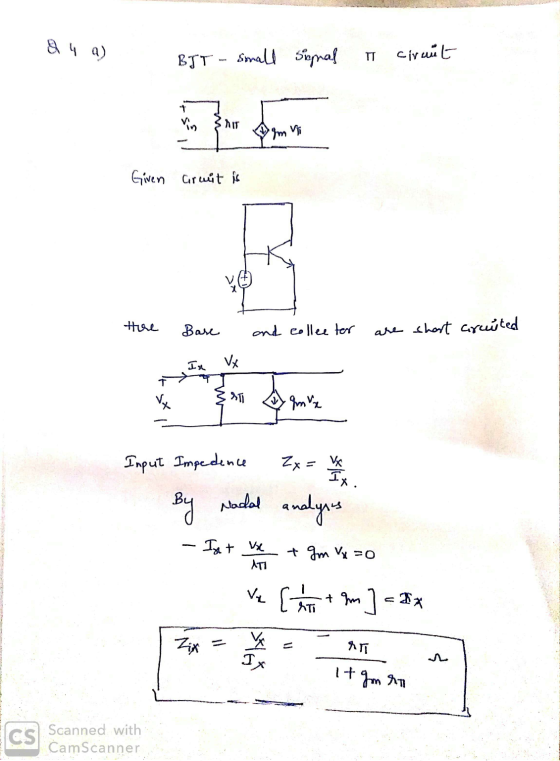
 Q. 4. (a) Draw a small signal equivalent circuit by replacing the BJT with its hybrid-1 model for the circuit shown below. Also derive an expression for Zin when ro is neglected. (iv) + Vx
Draw a small signal equivalent circuit by replacing the BJT with its hybrid-i model for the...
 Draw a small signal equivalent circuit by replacing the BJT with its hybrid-i model for the circuit shown below. Also derive an expression for Zin when rais neglected. + Vx
(b) Compute the voltage gain, input and output impedance for the following circuit if ß =...
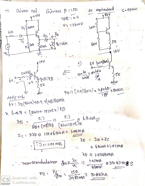
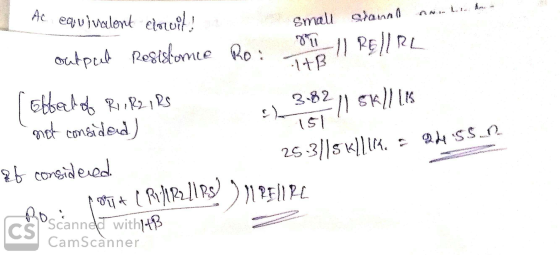
 (b) Compute the voltage gain, input and output impedance for the following circuit if ß = 150 and VBEQ = 0.7 V, V1 = 26 mV. A + 10 V 40 ΚΩ R1 4 ΚΩ Ci CO Vs R2 VO 60 ΚΩ 5 ΚΩ RE RL 1ΚΩ
Compute the voltage gain, input and output impedance for the following circuit if ß = 150...
 Compute the voltage gain, input and output impedance for the following circuit if ß = 150 and VBEQ = 0.7 V, VI = 26 mV. 4 + 10 V 40 ΚΩ R1 4 ΚΩ Ci CO Vs R2 VO 60 ΚΩ 5 ΚΩ RE R 1ΚΩ
2. For the common-emitter amplifier. B= 50. Vcc=12 a) Draw small signal circuit b) Find vout/vin...
 2. For the common-emitter amplifier. B= 50. Vcc=12 a) Draw small signal circuit b) Find vout/vin Find Zin and Zou Vcc R1 27k R2 2.2k Zout Zin Vo 4 C1 16 BIG Q1 NPN V1 C2 V R3 15k RE 1.2k BIG
7.53 For the circuit shown in Fig. P7.53, draw a complete small-signal equivalent circuit utilizing an...
 7.53 For the circuit shown in Fig. P7.53, draw a complete small-signal equivalent circuit utilizing an appropriate T model for the BJT (use a =0.99). Your circuit should show the values of all components, including the model parameters. What is the input resistance R ? Calculate the overall voltage gain (v,/v). (also find A, for this amp) sig +5 V RC 12 kΩ C2 RL 12 ΚΩ Rsig 75 N ) 0.33 mA Vsig Rin Figure P7.53
can you do 4.83 Ar- Q Sea 100 V, what does the gain become? age at...
 can
you do 4.83
Ar- Q Sea 100 V, what does the gain become? age at the collector. (b) Replacing the transistor by its T model, da the small-signal equivalent circuit of the a plifier. Analyze the resulting circuit to dete mine the voltage gain t/ 04.81 Consider the CE amplifier circuit of Fig. 4.43(a). It is required to design the circuit (i.e., find values for I and Rc) to meet the following specifications: (a) R,5kn (b) the voltage gain...
can
you do 4.83
Ar- Q Sea 100 V, what does the gain become? age at the collector. (b) Replacing the transistor by its T model, da the small-signal equivalent circuit of the a plifier. Analyze the resulting circuit to dete mine the voltage gain t/ 04.81 Consider the CE amplifier circuit of Fig. 4.43(a). It is required to design the circuit (i.e., find values for I and Rc) to meet the following specifications: (a) R,5kn (b) the voltage gain...
 Q. 4. (a) Draw a small signal equivalent circuit by replacing the BJT with its hybrid-1 model for the circuit shown below. Also derive an expression for Zin when ro is neglected. (iv) + Vx
 Draw a small signal equivalent circuit by replacing the BJT with its hybrid-i model for the circuit shown below. Also derive an expression for Zin when rais neglected. + Vx
 (b) Compute the voltage gain, input and output impedance for the following circuit if ß = 150 and VBEQ = 0.7 V, V1 = 26 mV. A + 10 V 40 ΚΩ R1 4 ΚΩ Ci CO Vs R2 VO 60 ΚΩ 5 ΚΩ RE RL 1ΚΩ
 Compute the voltage gain, input and output impedance for the following circuit if ß = 150 and VBEQ = 0.7 V, VI = 26 mV. 4 + 10 V 40 ΚΩ R1 4 ΚΩ Ci CO Vs R2 VO 60 ΚΩ 5 ΚΩ RE R 1ΚΩ
 2. For the common-emitter amplifier. B= 50. Vcc=12 a) Draw small signal circuit b) Find vout/vin Find Zin and Zou Vcc R1 27k R2 2.2k Zout Zin Vo 4 C1 16 BIG Q1 NPN V1 C2 V R3 15k RE 1.2k BIG
 7.53 For the circuit shown in Fig. P7.53, draw a complete small-signal equivalent circuit utilizing an appropriate T model for the BJT (use a =0.99). Your circuit should show the values of all components, including the model parameters. What is the input resistance R ? Calculate the overall voltage gain (v,/v). (also find A, for this amp) sig +5 V RC 12 kΩ C2 RL 12 ΚΩ Rsig 75 N ) 0.33 mA Vsig Rin Figure P7.53
 can
you do 4.83
Ar- Q Sea 100 V, what does the gain become? age at the collector. (b) Replacing the transistor by its T model, da the small-signal equivalent circuit of the a plifier. Analyze the resulting circuit to dete mine the voltage gain t/ 04.81 Consider the CE amplifier circuit of Fig. 4.43(a). It is required to design the circuit (i.e., find values for I and Rc) to meet the following specifications: (a) R,5kn (b) the voltage gain...
can
you do 4.83
Ar- Q Sea 100 V, what does the gain become? age at the collector. (b) Replacing the transistor by its T model, da the small-signal equivalent circuit of the a plifier. Analyze the resulting circuit to dete mine the voltage gain t/ 04.81 Consider the CE amplifier circuit of Fig. 4.43(a). It is required to design the circuit (i.e., find values for I and Rc) to meet the following specifications: (a) R,5kn (b) the voltage gain...
Most questions answered within 3 hours.
-
1.
Today Tomorrow
Price of Coke 1.90 2.10
Quantity of Pepsi 297 303
a. Write down...
asked 39 minutes ago -
Fluorine-20 has a half-life of 11.0 s. If a sample initially
contains 36.0 μg of this...
asked 1 hour ago -
How many fissions take place per second in a 190-MW reactor?
Assume 200 MeV is released...
asked 2 hours ago -
IQ scores are normally distributed with a mean of 100 and a
standard deviation of 15....
asked 2 hours ago -
You are to assess the biomechanics of a male’s arm using his
bicep to hold a...
asked 4 hours ago -
What is the maximum number of grams of N-acetyl-p-toluidine can
be prepared from 70. milliliters of...
asked 5 hours ago -
A researcher is using a two-tailed hypothesis test with α =
.05 to evaluate the effect...
asked 7 hours ago -
Two long, straight wires are parallel and 8.5 cm apart. The top
wire carries a current...
asked 8 hours ago -
Three arguments used to promote trade barriers are the national
security argument, the infant-industry argument, and...
asked 8 hours ago -
Question 3:
Percentage of Completion
Method (12 marks) On January 1, 2017, Eagle Construction Ltd.
started...
asked 8 hours ago -
A company purchased a tract of land for its natural resources at
a cost of $2,042,900....
asked 8 hours ago -
1. These financial statement item are
for UPS Company at fiscal year-end, October 31, 2019.
...
asked 8 hours ago