


Homework Answers


Add Answer to:
Learning Goal: To determine the angle of twist on a composite rod given the geometry and...
Learning Goal: To determine the angle of twist on a composite rod given the geometry and...
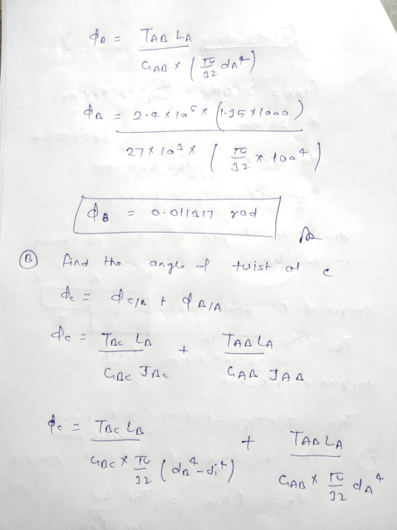
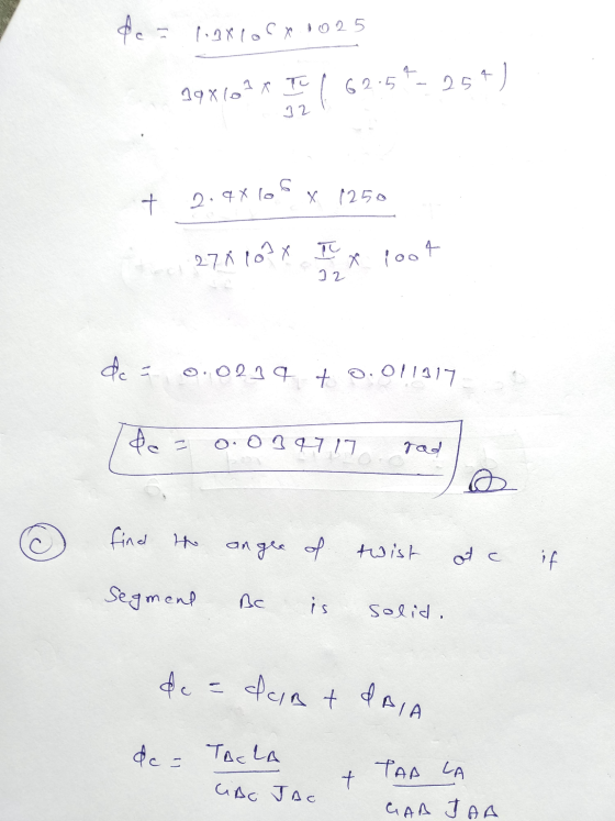
 Learning Goal: To determine the angle of twist on a composite rod given the geometry and externally applied torques, to properly apply a sign convention to determine the angle of twist, to use a torque diagram to aid in determining the angle of twist, and to determine the maximum applicable torque given a maximum allowable angle of twist. The rod shown below is made of two different materials. Segment AB is made of aluminum (G=27 GPa). Segment BC is bonded...
To determine the angle of twist on a composite rod given the geometry and externally applied...
 To determine the angle of twist on a composite rod given the geometry and externally applied torques, to properly apply a sign convention to determine the angle of twist, to use a torque diagram to aid in determining the angle of twist, and to determine the maximum applicable torque given a maximum allowable angle of twist. The rod shown below is made of two different materials. Segment AB is made of aluminum (G=3.9 x 10⁶ psi). Segment BC is bonded...
To determine the angle of twist on a composite rod given the geometry and externally applied...
 To determine the angle of twist on a composite rod given the geometry and externally applied torques, to properly apply a sign convention to determine the angle of twist, to use a torque diagram to aid in determining the angle of twist, and lo determine the maximum applicable lorque given a maximum allowable angle of wist. The rod shown below is made of two different materials. Segment AB is made of aluminum (G= 3.9 x 100 psi). Segment BC is...
Will rate!! CChaper 5 Torsion Angle of Twist 11 of 16 Learning Geal To determine the...
 Will rate!!
CChaper 5 Torsion Angle of Twist 11 of 16 Learning Geal To determine the angle of twist on a composite red gengeomebry and The rod showm below is made of two rgues, to propenty apply a sign convention to determine the angle of terist to usea torue diagram to aid in of twist, and to determine the maximum applicable toraue given a maimum alowable angle of wist and has an 6ameter eed.-,oin External towes sre spplied totho rod...
Will rate!!
CChaper 5 Torsion Angle of Twist 11 of 16 Learning Geal To determine the angle of twist on a composite red gengeomebry and The rod showm below is made of two rgues, to propenty apply a sign convention to determine the angle of terist to usea torue diagram to aid in of twist, and to determine the maximum applicable toraue given a maimum alowable angle of wist and has an 6ameter eed.-,oin External towes sre spplied totho rod...
Learning Goal: To determine the angle of twist for a circular shaft that is composed of...
 Learning Goal: To determine the angle of twist for a circular shaft that is composed of varying cross sections and that is subjected to a given power and frequency load. As shown, a shaft is composed of five cylindrical sections. A motor is attached at Fand supplies the shaft with P = 235.0 hp at a speed of w = 1800 rpm. This power is transferred through the shaft without any loss and is completely removed by the pulley at...
Learning Goal: To determine the state of stress in a solid rod using the principle of...
 Learning Goal: To determine the state of stress in a solid rod using the principle of superposition. A solid rod has a diameter of e = 55 mm and is subjected to the loading shown. Let a = 190 mm, b = 220 mm , c = 350 mm, d = 240 mm , and P = 4.0 kN. Take point A to be at the top of the circular cross-section. (Figure 1) Figure < 1 of 2 b В...
Learning Goal: To calculate torsional deformation and shear stress due to an applied force in a...
 Learning Goal: To calculate torsional deformation and shear stress due to an applied force in a door handle design. A locked door handle is composed of a solid circular shaft AB with a diameter fb = 105 mm and a flat plate BC with a force P = 76 N applied at point C as shown. Let c = 543 mm, d = 125 mm, and e = 145 mm. (Treat the handle as if it were a cantilever beam.)...
Learning Goal: To determine the angle of twist for a circular shaft that is composed of varying cross sections and that...
Learning Goal: To determine the angle of twist for a circular shaft that is composed of varying cross sections and that is subjected to a given power and frequency load. As shown, a shaft is composed of five cylindrical sections. A motor is attached at F and supplies the shaft with P = 235.0 hp at a speed of ω = 1800 rpm . This power is transferred through the shaft without any loss and is completely removed by the...
Part A - Moment about the x axis at A Learning Goal: To determine the state...
 Part A - Moment about the x axis at A Learning Goal: To determine the state of stress in a solid rod using the principle of superposition. A solid rod has a diameter of e = 60 mm and is subjected to the loading shown. Let a = 200 mm, b = 220 mm c = 340 mm, d = 230 mm, and P = 4.0 kN. Take point A to be at the top of the circular cross-section. (Figure...
Torsional Deformation of a Circular Shaft Learning Goal: To calculate torsional deformation and s...
 Torsional Deformation of a Circular Shaft Learning Goal: To calculate torsional deformation and shear stress due to an applied force in a door handle design. A locked door handle is composed of a solid orcular shaft AB with a diameter of b 101 mm and a flat plate BC with a ferce P-65 N applied at point C as shown Let c 523 mm,d 135 mm, and e 157 mm (Treat the hande as if it were a cantilever beam)...
 Learning Goal: To determine the angle of twist on a composite rod given the geometry and externally applied torques, to properly apply a sign convention to determine the angle of twist, to use a torque diagram to aid in determining the angle of twist, and to determine the maximum applicable torque given a maximum allowable angle of twist. The rod shown below is made of two different materials. Segment AB is made of aluminum (G=27 GPa). Segment BC is bonded...
 To determine the angle of twist on a composite rod given the geometry and externally applied torques, to properly apply a sign convention to determine the angle of twist, to use a torque diagram to aid in determining the angle of twist, and to determine the maximum applicable torque given a maximum allowable angle of twist. The rod shown below is made of two different materials. Segment AB is made of aluminum (G=3.9 x 10⁶ psi). Segment BC is bonded...
 To determine the angle of twist on a composite rod given the geometry and externally applied torques, to properly apply a sign convention to determine the angle of twist, to use a torque diagram to aid in determining the angle of twist, and lo determine the maximum applicable lorque given a maximum allowable angle of wist. The rod shown below is made of two different materials. Segment AB is made of aluminum (G= 3.9 x 100 psi). Segment BC is...
 Will rate!!
CChaper 5 Torsion Angle of Twist 11 of 16 Learning Geal To determine the angle of twist on a composite red gengeomebry and The rod showm below is made of two rgues, to propenty apply a sign convention to determine the angle of terist to usea torue diagram to aid in of twist, and to determine the maximum applicable toraue given a maimum alowable angle of wist and has an 6ameter eed.-,oin External towes sre spplied totho rod...
Will rate!!
CChaper 5 Torsion Angle of Twist 11 of 16 Learning Geal To determine the angle of twist on a composite red gengeomebry and The rod showm below is made of two rgues, to propenty apply a sign convention to determine the angle of terist to usea torue diagram to aid in of twist, and to determine the maximum applicable toraue given a maimum alowable angle of wist and has an 6ameter eed.-,oin External towes sre spplied totho rod...
 Learning Goal: To determine the angle of twist for a circular shaft that is composed of varying cross sections and that is subjected to a given power and frequency load. As shown, a shaft is composed of five cylindrical sections. A motor is attached at Fand supplies the shaft with P = 235.0 hp at a speed of w = 1800 rpm. This power is transferred through the shaft without any loss and is completely removed by the pulley at...
 Learning Goal: To determine the state of stress in a solid rod using the principle of superposition. A solid rod has a diameter of e = 55 mm and is subjected to the loading shown. Let a = 190 mm, b = 220 mm , c = 350 mm, d = 240 mm , and P = 4.0 kN. Take point A to be at the top of the circular cross-section. (Figure 1) Figure < 1 of 2 b В...
 Learning Goal: To calculate torsional deformation and shear stress due to an applied force in a door handle design. A locked door handle is composed of a solid circular shaft AB with a diameter fb = 105 mm and a flat plate BC with a force P = 76 N applied at point C as shown. Let c = 543 mm, d = 125 mm, and e = 145 mm. (Treat the handle as if it were a cantilever beam.)...
 Part A - Moment about the x axis at A Learning Goal: To determine the state of stress in a solid rod using the principle of superposition. A solid rod has a diameter of e = 60 mm and is subjected to the loading shown. Let a = 200 mm, b = 220 mm c = 340 mm, d = 230 mm, and P = 4.0 kN. Take point A to be at the top of the circular cross-section. (Figure...
 Torsional Deformation of a Circular Shaft Learning Goal: To calculate torsional deformation and shear stress due to an applied force in a door handle design. A locked door handle is composed of a solid orcular shaft AB with a diameter of b 101 mm and a flat plate BC with a ferce P-65 N applied at point C as shown Let c 523 mm,d 135 mm, and e 157 mm (Treat the hande as if it were a cantilever beam)...
Most questions answered within 3 hours.
-
A .15kg rubber ball is bounced off a wall. Before hitting the
wall, the ball moves...
asked 27 minutes ago -
A manufacturing company preparing to build a new plant is
considering three potential locations for it....
asked 29 minutes ago -
B. If compound Y has approximately the same values of solubility
in toluene as compound X,...
asked 1 hour ago -
Oscar Inc. has inventory in Japan valued at 39,051,000 Yen one
year ago. One year ago...
asked 1 hour ago -
If Canada suffered from "fundamental disequilibrium," and its
government choose not to devalue its currency, a...
asked 1 hour ago -
4. How many input & output Key Value Pairs are passed into,
and emitted out of...
asked 1 hour ago -
Why would your heart not function well if constructed of
skeletal muscle? What is the particular...
asked 1 hour ago -
Please respond to this essay question in full essay form for
Chemistry 1102 Organic and Biochemistry:...
asked 1 hour ago -
Determine the head loss and velocity of flow in a water supply main
of 15.0 cm...
asked 1 hour ago -
A marketing executive who knowingly authorizes a shoddy
defective product to be brought to market is...
asked 1 hour ago -
Write a psudocode:
1. Define a function called authorize that takes in 2 strings,
uName, and...
asked 1 hour ago -
What Hall voltage (in mV) is produced by a 0.180 T field applied
across a 2.60...
asked 1 hour ago