

Homework Answers
Please give me rating if you like my work.
Thank you so much in advance!!!
Add Answer to:
Learning Goal: To analyze two bullt-up members that have the same geometry but are fastened differently,...
To analyze two built-up members that have the same geometry but are fastened differently, determine the...
 To analyze two built-up members that have the same geometry but
are fastened differently, determine the maximum applicable shear
force on each cross section, and determine the adjustment in
spacing between the weaker member’s fasteners that would allow the
member to support the equivalent maximum shear force of the
stronger member.
The two cross sections shown below, (a) and
(b), are subjected to a vertical shear force as shown. The
members are fastened by nails that can support a load...
To analyze two built-up members that have the same geometry but
are fastened differently, determine the maximum applicable shear
force on each cross section, and determine the adjustment in
spacing between the weaker member’s fasteners that would allow the
member to support the equivalent maximum shear force of the
stronger member.
The two cross sections shown below, (a) and
(b), are subjected to a vertical shear force as shown. The
members are fastened by nails that can support a load...
To analyze two built-up members that have the same geometry but are fastened differently, determine the...
To analyze two built-up members that have the same geometry but are fastened differently, determine the maximum applicable shear force on each cross section, and determine the adjustment in spacing between the weaker member’s fasteners that would allow the member to support the equivalent maximum shear force of the stronger member. The two cross sections shown below, (a) and (b), are subjected to a vertical shear force as shown. The members are fastened by nails that can support a load...
The two cross sections shown below, (a) and (b), are subjected to a vertical shear force...
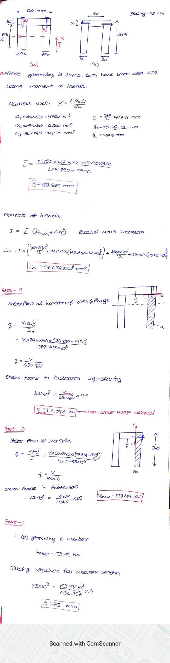
 The two cross sections shown below, (a) and (b), are subjected to a vertical shear force as shown. The members are fastened by nails that can support a load of 21.00 kN each and are spaced perpendicularly to the page in increments of s = 105.0 mm. The geometries of the cross sections are given by a = 250.0 mm, b = 50.00 mm, c = 255.0 mm, d = 150 mm, and e = 305 mm Assume the cross...
Please find the maximum applicable shear force on member a and member b. Then the required...
 Please find the maximum applicable shear force on
member a and member b. Then the required spacing in the weaker
member such that both cross sections can support the same
maximum applicable
force as defined by the stronger member.
Having trouble with the equations and I'm not really
sure where I'm going wrong. Work would be appreciated. Thank
you!!
5 of 6 Learning Goal: To analyze two built-up members that have the same geometry but are fastened differently, determine the...
Please find the maximum applicable shear force on
member a and member b. Then the required spacing in the weaker
member such that both cross sections can support the same
maximum applicable
force as defined by the stronger member.
Having trouble with the equations and I'm not really
sure where I'm going wrong. Work would be appreciated. Thank
you!!
5 of 6 Learning Goal: To analyze two built-up members that have the same geometry but are fastened differently, determine the...
Learning Goal: To determine the maximum shear force that can be applied to two shafts of...
 Learning Goal: To determine the maximum shear force that can be applied to two shafts of varying cross sections: a solid square shaft and a hollow square shaft. The two square cross sections shown below (Figure 1) are each subjected to a vertical shear force, V. The side length of each cross section is s = 6.00 in and the side length of the hollowed- out portion of the second cross section is r = 2.25 in. The maximum allowable...
Learning Goal: To calculate torsional deformation and shear stress due to an applied force in a...
 Learning Goal: To calculate torsional deformation and shear stress due to an applied force in a door handle design. A locked door handle is composed of a solid circular shaft AB with a diameter fb = 105 mm and a flat plate BC with a force P = 76 N applied at point C as shown. Let c = 543 mm, d = 125 mm, and e = 145 mm. (Treat the handle as if it were a cantilever beam.)...
Learning Goal: To calculate torsional deformation and shear stress due to an applied force in a...
 Learning Goal: To calculate torsional deformation and shear stress due to an applied force in a door handle design. A locked door handle is composed of a solid circular shaft AB with a diameter of b = 101 mm and a flat plate BC with a force P = 77 N applied at point C as shown. Let c = 473 mm, d = 126 mm, and e = 148 mm (Treat the handle as if it were a cantilever...
Torsional Deformation of a Circular Shaft Learning Goal: To calculate torsional deformation and s...
 Torsional Deformation of a Circular Shaft Learning Goal: To calculate torsional deformation and shear stress due to an applied force in a door handle design. A locked door handle is composed of a solid orcular shaft AB with a diameter of b 101 mm and a flat plate BC with a ferce P-65 N applied at point C as shown Let c 523 mm,d 135 mm, and e 157 mm (Treat the hande as if it were a cantilever beam)...
Learning Goal: To calculate torsional deformation and shear stress due to an applied force in a...
 Learning Goal: To calculate torsional deformation and shear stress due to an applied force in a door handle design. A locked door handle is composed of a solid circular shaft AB with a diameter fb = 105 mm and a flat plate BC with a force P = 76 N applied at point C as shown. Let c = 543 mm, d = 125 mm, and e = 145 mm. (Treat the handle as if it were a cantilever beam.)...
Leaming Goal: To determine the shear stresses at specific locations in a beam due to an...
 Leaming Goal: To determine the shear stresses at specific locations in a beam due to an external loading. Beam ABC is subjected to the loading shown, where PB = 40.0 kN. The measurement corresponding to the half-length of the beam is a = 2.50 m. For the cross section shown, b = 50.0 mm, c= 125.0 mm, d = 125.0 mm, and e = 65.0 mm Point Dis located at the centroid of the cross section and point E is...
 To analyze two built-up members that have the same geometry but
are fastened differently, determine the maximum applicable shear
force on each cross section, and determine the adjustment in
spacing between the weaker member’s fasteners that would allow the
member to support the equivalent maximum shear force of the
stronger member.
The two cross sections shown below, (a) and
(b), are subjected to a vertical shear force as shown. The
members are fastened by nails that can support a load...
To analyze two built-up members that have the same geometry but
are fastened differently, determine the maximum applicable shear
force on each cross section, and determine the adjustment in
spacing between the weaker member’s fasteners that would allow the
member to support the equivalent maximum shear force of the
stronger member.
The two cross sections shown below, (a) and
(b), are subjected to a vertical shear force as shown. The
members are fastened by nails that can support a load...
 The two cross sections shown below, (a) and (b), are subjected to a vertical shear force as shown. The members are fastened by nails that can support a load of 21.00 kN each and are spaced perpendicularly to the page in increments of s = 105.0 mm. The geometries of the cross sections are given by a = 250.0 mm, b = 50.00 mm, c = 255.0 mm, d = 150 mm, and e = 305 mm Assume the cross...
 Please find the maximum applicable shear force on
member a and member b. Then the required spacing in the weaker
member such that both cross sections can support the same
maximum applicable
force as defined by the stronger member.
Having trouble with the equations and I'm not really
sure where I'm going wrong. Work would be appreciated. Thank
you!!
5 of 6 Learning Goal: To analyze two built-up members that have the same geometry but are fastened differently, determine the...
Please find the maximum applicable shear force on
member a and member b. Then the required spacing in the weaker
member such that both cross sections can support the same
maximum applicable
force as defined by the stronger member.
Having trouble with the equations and I'm not really
sure where I'm going wrong. Work would be appreciated. Thank
you!!
5 of 6 Learning Goal: To analyze two built-up members that have the same geometry but are fastened differently, determine the...
 Learning Goal: To determine the maximum shear force that can be applied to two shafts of varying cross sections: a solid square shaft and a hollow square shaft. The two square cross sections shown below (Figure 1) are each subjected to a vertical shear force, V. The side length of each cross section is s = 6.00 in and the side length of the hollowed- out portion of the second cross section is r = 2.25 in. The maximum allowable...
 Learning Goal: To calculate torsional deformation and shear stress due to an applied force in a door handle design. A locked door handle is composed of a solid circular shaft AB with a diameter fb = 105 mm and a flat plate BC with a force P = 76 N applied at point C as shown. Let c = 543 mm, d = 125 mm, and e = 145 mm. (Treat the handle as if it were a cantilever beam.)...
 Learning Goal: To calculate torsional deformation and shear stress due to an applied force in a door handle design. A locked door handle is composed of a solid circular shaft AB with a diameter of b = 101 mm and a flat plate BC with a force P = 77 N applied at point C as shown. Let c = 473 mm, d = 126 mm, and e = 148 mm (Treat the handle as if it were a cantilever...
 Torsional Deformation of a Circular Shaft Learning Goal: To calculate torsional deformation and shear stress due to an applied force in a door handle design. A locked door handle is composed of a solid orcular shaft AB with a diameter of b 101 mm and a flat plate BC with a ferce P-65 N applied at point C as shown Let c 523 mm,d 135 mm, and e 157 mm (Treat the hande as if it were a cantilever beam)...
 Learning Goal: To calculate torsional deformation and shear stress due to an applied force in a door handle design. A locked door handle is composed of a solid circular shaft AB with a diameter fb = 105 mm and a flat plate BC with a force P = 76 N applied at point C as shown. Let c = 543 mm, d = 125 mm, and e = 145 mm. (Treat the handle as if it were a cantilever beam.)...
 Leaming Goal: To determine the shear stresses at specific locations in a beam due to an external loading. Beam ABC is subjected to the loading shown, where PB = 40.0 kN. The measurement corresponding to the half-length of the beam is a = 2.50 m. For the cross section shown, b = 50.0 mm, c= 125.0 mm, d = 125.0 mm, and e = 65.0 mm Point Dis located at the centroid of the cross section and point E is...
Most questions answered within 3 hours.
-
39.4% of US homes continue to use a landline in addition to cell
phone service. 3...
asked 11 minutes ago -
Starting with benzene, synthesize 1-phenyl-1-butyne.
Show intermediates and reagents.
asked 1 hour ago -
Create a 32-run crossed array design with six control factors
and two noise factors such that...
asked 2 hours ago -
A 500g sample of sand from source A has the following amounts
retained on each sieve....
asked 2 hours ago -
In
your own words, please explain the essay by John Keynes wrote "The
End of Laissez...
asked 2 hours ago -
How are the matrix and pixels related? Why are smaller
pixels better for diagnostic quality?
asked 2 hours ago -
2. An AC generator has 80 rectangular loops on
its armature. Each loop is 11 cm...
asked 2 hours ago -
Please help me with this question. Consider Aldi’s current and
potential geographic markets (see Exhibit 4...
asked 2 hours ago -
What are the main components of the fermentation process and
give an explanation of each? Include...
asked 2 hours ago -
Explain which types of cells in the body (belonging to which
organs, etc.) are sensitive to...
asked 2 hours ago -
A single cable supports an 703-kg elevator car. What is the
tension in the cable when...
asked 2 hours ago -
among the three different ways to link CSS specifications to an
HTML document (inline CSS, document...
asked 2 hours ago