You will use Quartus II to build an 8 bit arithmetic logic unit that performs the...
You will use Quartus II to build an 8 bit arithmetic logic unit that performs the following functions:
| Control Value | Function |
| 000 | Copy In1 to theResult unchanged |
| 001 | Copy In2 to theResult unchanged |
| 010 | Add In1 to In2 |
| 011 | Subtract In2 from In1 |
| 100 | And In1 and In2 |
| 101 | Or In1 and In2 |
| 110 | Shift left In1 by 1 bit |
| 111 | Shift right In1 by 1 bit |
You are allowed to use either gates/logic schematic, or else Verilog. We suggest that you use Verilog.
You are given a starter lab, in the directory HW Lab ALU. This contains a “starter” Verilog module, and an associated schematic block diagram of the inputs and outputs expected for the ALU:
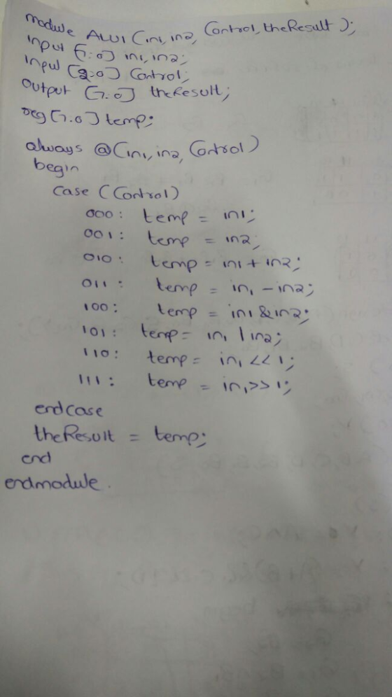
module ALU1(In1,In2, Control, theResult);
input [7:0] In1, In2;
input[3:0] Control;
output [7:0] theResult;
// Insert your code here
endmodule
If you decide to use Verilog, you may find the following code useful:
reg [7:0] temp_theResult;
temp_theResult=In1;(this would need to be in an ‘if’ or ‘case’ statement) assign theResult = temp_theResult;
Explanation: temp_theResult is a variable (stored in a register), whereas theResult is net (actual wires). In certain coding situations you may not be able to write some values directly to theResult, they may need to be written to a variable first.
Useful Verilog Hints:
1. You can represent a 4 bit binary number as: • 4'b0000
2. A case statement in Verilog would look like this:
always @(Control, In1, In2)
begin
case(Control) value0: code statement; value1: code statement;
end
• The always block executes all the time (always), as opposed to initial blocks that only execute one time at the beginning of simulation
• The @ symbol indicates that the always block will be “triggered” whenever the specified variables change 3. Various operators include:
• + is add
• - is subtract
• & is and
• | is or
• A<<1 is shift A left by 1 bit
• A>>1 is shift A right by 1 bit
Homework Answers
Add Answer to:
You will use Quartus II to build an 8 bit arithmetic logic unit
that performs the...
The Arithmetic Logic Unit The first topic for the project is to create an Arithmetic Logic...
The Arithmetic Logic Unit The first topic for the project is to create an Arithmetic Logic Unit, using a structured approached with a Virtual Hardware Design Language such as Verilog. Mainly, the program is very close to a simulator for a programming calculator. An ALU typically has the following operations Math Functions: Add, Subtract, Multiply, Divide, Modulus Logic Functions: And, Or, XOR, Not, Nand, Nor, XNOR Error Modes: Divide by Zero, Overflow Support Functions: No Operation, Shift Left, Shift Right,...
Q2. Design a 8-bit ALU (Arithmetic Logic Unit) supporting the following instructions, Z and C values...
 Q2. Design a 8-bit ALU (Arithmetic Logic Unit) supporting the following instructions, Z and C values should be re-evaluated (updated) ifY changes Instruction type code[2:0] operations Logical Status update 001 010 011 100 101 110 ( Bitwise AND) Y = A & B: | Z (C is always 0) (bitwise OR) Y- A B; (bitwise XOR) Y-A B Z (Cis always 0) (negation) Y =-A; (Addition) Y A + B: (subtraction) Y = A-B: (Increment) Y-A+1 (decrement) Y-A-1 Z (C...
This section gives you freedom to come up with your own solutions. An Arithmetic and Logic Unit (...
 This section gives you freedom to come up with your own
solutions.
An Arithmetic and Logic Unit (ALU) is a combinational circuit
that performs logic and arithmetic micro-operations on a pair of
4-bit operands. The operations performed by an ALU are controlled
by a set of function-select inputs. In this lab you will
design a 4-bit ALU with 3 function-select inputs: Mode M, Select S1
and S0 inputs. The mode input M selects between a Logic (M=0) and
Arithmetic (M=1)...
This section gives you freedom to come up with your own
solutions.
An Arithmetic and Logic Unit (ALU) is a combinational circuit
that performs logic and arithmetic micro-operations on a pair of
4-bit operands. The operations performed by an ALU are controlled
by a set of function-select inputs. In this lab you will
design a 4-bit ALU with 3 function-select inputs: Mode M, Select S1
and S0 inputs. The mode input M selects between a Logic (M=0) and
Arithmetic (M=1)...
Derive the logic gates for a 2-bit Arithmetic Logic Unit (ALU) with four micro-operations: 1) Complete...
 Derive the logic gates for a 2-bit Arithmetic Logic Unit (ALU)
with four micro-operations:
1) Complete the table below by showing the select input bits and the necessary groupings. (5 points) Select Inputs Micro-Operation Description F = A-B-1 F = A + B +1 F = AVB F = ashl A Subtraction with borrow Addition with carry Logic OR Arithmetic shift left 2) Draw a detailed logic circuit of the ALU's arithmetic unit. (10 points) 3) Draw a detailed logic...
Derive the logic gates for a 2-bit Arithmetic Logic Unit (ALU)
with four micro-operations:
1) Complete the table below by showing the select input bits and the necessary groupings. (5 points) Select Inputs Micro-Operation Description F = A-B-1 F = A + B +1 F = AVB F = ashl A Subtraction with borrow Addition with carry Logic OR Arithmetic shift left 2) Draw a detailed logic circuit of the ALU's arithmetic unit. (10 points) 3) Draw a detailed logic...
Design a 4-bit Arithmetic Logic Unit (ALU) according to the following specification
 Design a 4-bit Arithmetic Logic Unit (ALU) according to the following specification. Follow the design shown during the lecture. Notice this table is different, though. a. Create the internal of 1-bit of the logic unit (It is recommended that you design the internal of a 4 to 1 MUX first, create a symbol for it and use it for creating the logic unit) b. Create a symbol for your logic unit and use four of them to make a 4-bit logic unit c....
The assignment is build an 8 bit ALU in structural verilog NOT behavioral : Requirements are to design the ALU to implement NAND, AND, OR, NOT, XOR, XNOR, ADD, SUBTRACT, COMPARE, etc. WIll be executed...
The assignment is build an 8 bit ALU in structural verilog NOT behavioral : Requirements are to design the ALU to implement NAND, AND, OR, NOT, XOR, XNOR, ADD, SUBTRACT, COMPARE, etc. WIll be executed on 2s complemented throughout. 15 Op codes necessary are the following: -Transfer A -Increment A -Addition -Subtraction -Decrement A -1s comp -A and B,A NAND B,A or B, A NOR B, A XOR B, A XNOR B, -A greater than B -A Les than B...
Using Structural Modeling in VHDL write the code for: An Arithmetic Logic Unit (ALU) shown in...
 Using Structural Modeling in VHDL write the
code for:
An Arithmetic Logic Unit (ALU) shown in the
figure below. A (16-bit), B
(16-bit), Opcode (3-bit), and
Mode (1-bit) are the inputs; and
ALUOut (16-bit) and Cout (1-bit) are the outputs
of the design. A and B hold the values of the operands. Mode and
Opcode together indicate the type of the operation performed by
ALU.
The ALU components ARE:
-Arithmetic Unit that consists of one 16-bit
adder, 16-bit subtractor, 16-bit...
Using Structural Modeling in VHDL write the
code for:
An Arithmetic Logic Unit (ALU) shown in the
figure below. A (16-bit), B
(16-bit), Opcode (3-bit), and
Mode (1-bit) are the inputs; and
ALUOut (16-bit) and Cout (1-bit) are the outputs
of the design. A and B hold the values of the operands. Mode and
Opcode together indicate the type of the operation performed by
ALU.
The ALU components ARE:
-Arithmetic Unit that consists of one 16-bit
adder, 16-bit subtractor, 16-bit...
Use the Quartus Prime Text Editor to implement a structural model of the 4-bit data register show...
 Use the Quartus Prime Text Editor to implement a structural
model of the 4-bit data register shown above in a file named
reg_4bit.sv. Specify the 4-bit data register’s module according to
the interface specification given in the table below.
Port
Mode
Data Type
Size
Description
RST
in
logic
1-bit
Active high asynchronous reset
CLK
in
logic
1-bit
Synchronizing clock signal
EN
in
logic
1-bit
Synchronous clock enable
D
in
logic vector
4-bits
Synchronous data input
Q
out
logic vector
4-bits...
Use the Quartus Prime Text Editor to implement a structural
model of the 4-bit data register shown above in a file named
reg_4bit.sv. Specify the 4-bit data register’s module according to
the interface specification given in the table below.
Port
Mode
Data Type
Size
Description
RST
in
logic
1-bit
Active high asynchronous reset
CLK
in
logic
1-bit
Synchronizing clock signal
EN
in
logic
1-bit
Synchronous clock enable
D
in
logic vector
4-bits
Synchronous data input
Q
out
logic vector
4-bits...
FIRST ACTIVITY: (100/100) . SIMPLE 4-BIT ARITHMETIC LOGIC UNIT (ALU): This circuit selects between arithmetic (absolute...
 FIRST ACTIVITY: (100/100) . SIMPLE 4-BIT ARITHMETIC LOGIC UNIT (ALU): This circuit selects between arithmetic (absolute value, addition) and logical (XOR, AND) operations. Only one result (hexadecimal value) can be shown on the 7-segment display This is selected by the input sel (1..0) B A-BI A+B A xnor B A nand B Input EN: If EN-1result appears on the 7 segment display. If EN=0 → all LEDs in the 7 segment display are off Arithmetic operations: The 4-bit inputs A...
Write a testbench for use in Quartus' ModelSim Altera in verilog for the following code of...
Write a testbench for use in Quartus' ModelSim Altera in verilog for the following code of a 4x16 register: module regFile4x16 (input clk, input write, input [2:0] wrAddr, input [15:0] wrData, input [2:0] rdAddrA, output [15:0] rdDataA, input [2:0] rdAddrB, output [15:0] rdDataB); reg [15:0] reg0, reg1, reg2, reg3; assign rdDataA = rdAddrA == 0 ? reg0 : rdAddrA == 1 ? reg1 : rdAddrA == 2 ? reg2 : rdAddrA == 3...
 Q2. Design a 8-bit ALU (Arithmetic Logic Unit) supporting the following instructions, Z and C values should be re-evaluated (updated) ifY changes Instruction type code[2:0] operations Logical Status update 001 010 011 100 101 110 ( Bitwise AND) Y = A & B: | Z (C is always 0) (bitwise OR) Y- A B; (bitwise XOR) Y-A B Z (Cis always 0) (negation) Y =-A; (Addition) Y A + B: (subtraction) Y = A-B: (Increment) Y-A+1 (decrement) Y-A-1 Z (C...
 This section gives you freedom to come up with your own
solutions.
An Arithmetic and Logic Unit (ALU) is a combinational circuit
that performs logic and arithmetic micro-operations on a pair of
4-bit operands. The operations performed by an ALU are controlled
by a set of function-select inputs. In this lab you will
design a 4-bit ALU with 3 function-select inputs: Mode M, Select S1
and S0 inputs. The mode input M selects between a Logic (M=0) and
Arithmetic (M=1)...
This section gives you freedom to come up with your own
solutions.
An Arithmetic and Logic Unit (ALU) is a combinational circuit
that performs logic and arithmetic micro-operations on a pair of
4-bit operands. The operations performed by an ALU are controlled
by a set of function-select inputs. In this lab you will
design a 4-bit ALU with 3 function-select inputs: Mode M, Select S1
and S0 inputs. The mode input M selects between a Logic (M=0) and
Arithmetic (M=1)...
 Derive the logic gates for a 2-bit Arithmetic Logic Unit (ALU)
with four micro-operations:
1) Complete the table below by showing the select input bits and the necessary groupings. (5 points) Select Inputs Micro-Operation Description F = A-B-1 F = A + B +1 F = AVB F = ashl A Subtraction with borrow Addition with carry Logic OR Arithmetic shift left 2) Draw a detailed logic circuit of the ALU's arithmetic unit. (10 points) 3) Draw a detailed logic...
Derive the logic gates for a 2-bit Arithmetic Logic Unit (ALU)
with four micro-operations:
1) Complete the table below by showing the select input bits and the necessary groupings. (5 points) Select Inputs Micro-Operation Description F = A-B-1 F = A + B +1 F = AVB F = ashl A Subtraction with borrow Addition with carry Logic OR Arithmetic shift left 2) Draw a detailed logic circuit of the ALU's arithmetic unit. (10 points) 3) Draw a detailed logic...
 Using Structural Modeling in VHDL write the
code for:
An Arithmetic Logic Unit (ALU) shown in the
figure below. A (16-bit), B
(16-bit), Opcode (3-bit), and
Mode (1-bit) are the inputs; and
ALUOut (16-bit) and Cout (1-bit) are the outputs
of the design. A and B hold the values of the operands. Mode and
Opcode together indicate the type of the operation performed by
ALU.
The ALU components ARE:
-Arithmetic Unit that consists of one 16-bit
adder, 16-bit subtractor, 16-bit...
Using Structural Modeling in VHDL write the
code for:
An Arithmetic Logic Unit (ALU) shown in the
figure below. A (16-bit), B
(16-bit), Opcode (3-bit), and
Mode (1-bit) are the inputs; and
ALUOut (16-bit) and Cout (1-bit) are the outputs
of the design. A and B hold the values of the operands. Mode and
Opcode together indicate the type of the operation performed by
ALU.
The ALU components ARE:
-Arithmetic Unit that consists of one 16-bit
adder, 16-bit subtractor, 16-bit...
 Use the Quartus Prime Text Editor to implement a structural
model of the 4-bit data register shown above in a file named
reg_4bit.sv. Specify the 4-bit data register’s module according to
the interface specification given in the table below.
Port
Mode
Data Type
Size
Description
RST
in
logic
1-bit
Active high asynchronous reset
CLK
in
logic
1-bit
Synchronizing clock signal
EN
in
logic
1-bit
Synchronous clock enable
D
in
logic vector
4-bits
Synchronous data input
Q
out
logic vector
4-bits...
Use the Quartus Prime Text Editor to implement a structural
model of the 4-bit data register shown above in a file named
reg_4bit.sv. Specify the 4-bit data register’s module according to
the interface specification given in the table below.
Port
Mode
Data Type
Size
Description
RST
in
logic
1-bit
Active high asynchronous reset
CLK
in
logic
1-bit
Synchronizing clock signal
EN
in
logic
1-bit
Synchronous clock enable
D
in
logic vector
4-bits
Synchronous data input
Q
out
logic vector
4-bits...
 FIRST ACTIVITY: (100/100) . SIMPLE 4-BIT ARITHMETIC LOGIC UNIT (ALU): This circuit selects between arithmetic (absolute value, addition) and logical (XOR, AND) operations. Only one result (hexadecimal value) can be shown on the 7-segment display This is selected by the input sel (1..0) B A-BI A+B A xnor B A nand B Input EN: If EN-1result appears on the 7 segment display. If EN=0 → all LEDs in the 7 segment display are off Arithmetic operations: The 4-bit inputs A...
Most questions answered within 3 hours.
-
Calculate and plot the number and weight distributions of x-mers
found in a step-growth polymerization for...
asked 5 minutes ago -
The Baily Corporation has developed a specialized software
program that improves inventory control capability. The following...
asked 8 minutes ago -
Problem 5-4A (Part Level Submission) Wolford Department Store is
located in midtown Metropolis. During the past...
asked 8 minutes ago -
Preparation of Benzoic Acid using a Grignard Reagent URGENT
1. During your Grignard formation, a small...
asked 31 minutes ago -
A uniform magnetic field is perpendicular to the plane of a wire
loop. If the loop...
asked 30 minutes ago -
At the peak of your career, your were earning $120,000 and
holding a top level position....
asked 33 minutes ago -
. A permanent magnet is dropped south-end-down through a horizontal
circular coil with a radius of...
asked 36 minutes ago -
Bernie's Beverages purchased some fixed assets classified as
5-year property for MACRS. The assets cost $28,000....
asked 50 minutes ago -
How many ATPs are produced from the catabolism of a 10-C
molecule of fatty acid under...
asked 54 minutes ago -
Before practicing a routine on the rings, a 64.8 kg gymnast
hangs motionless, with one hand...
asked 56 minutes ago -
If the K b of a weak base is 6.3 × 10 − 6 , what...
asked 1 hour ago -
Which of the following is the minimum amount of moles of NaOH
that must be added...
asked 1 hour ago