
Homework Answers

Add Answer to:
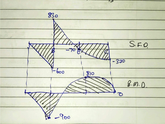
A beam is subjected to distributed loading as shown in Figure Q4. (a) Determine the reaction...
The cantilever beam shown is subjected to a moment at A and a distributed load that...
 The cantilever beam shown is subjected to a moment at A and a
distributed load that acts over segment BC, and is fixed at C.
Determine the reactions at the support located at C. Then write
expressions for shear and bending moment as a function of their
positions along the beam. Finally, use these expressions to
construct shear and bending moment diagrams.
Part A - Reactions at support C
Draw a free-body diagram of the beam on paper. Use your...
The cantilever beam shown is subjected to a moment at A and a
distributed load that acts over segment BC, and is fixed at C.
Determine the reactions at the support located at C. Then write
expressions for shear and bending moment as a function of their
positions along the beam. Finally, use these expressions to
construct shear and bending moment diagrams.
Part A - Reactions at support C
Draw a free-body diagram of the beam on paper. Use your...
1. For the simply supported beam subjected to the loading shown, Derive equations for the shear...
 1. For the simply supported beam subjected to the loading shown, Derive equations for the shear force V and the bending moment M for any location in the beam. (Place the origin at point A.) a. b. Plot the shear-force and bending-moment diagrams for the beam using the derived functions c. Report the maximum bending moment and its location. 42 kips 6 kips/ft 10 ft 20 ft
2. For the beam and loading shown in the following figure: (a) find all the reaction...
 2. For the beam and loading shown in the following figure: (a) find all the reaction forces, (b) draw the shear and bending moment diagrams and (c) determine the maximum absolute value of the shear and the bending moment. 25 kN m 40 kN 401N 0.61 1.S 0.6 m
QUESTION 1 [15] For the simply supported beam subjected to the loading shown in the figure,...
 QUESTION 1 [15] For the simply supported beam subjected to the loading shown in the figure, a) Derive equations for the shear force V and the bending moment M for any location in the beam. (Place the origin at point A.) b) Report the maximum positive bending moment, the maximum negative bending moment, and their respective locations. 36 KN 180 KN-m X B C D 4 m 5 m 3 m Figure 1
The cantilever beam shown is subjected to a moment at A and a distributed load that...
 The cantilever beam shown is subjected to a moment at A
and a distributed load that acts over segment BC, and is
fixed at C. Determine the reactions at the support located
at C. Then write expressions for shear and bending moment
as a function of their positions along the beam. Finally, use these
expressions to construct shear and bending moment diagrams
Draw a free-body diagram of the beam on paper. Use your
free-body diagram to determine the reactions at...
The cantilever beam shown is subjected to a moment at A
and a distributed load that acts over segment BC, and is
fixed at C. Determine the reactions at the support located
at C. Then write expressions for shear and bending moment
as a function of their positions along the beam. Finally, use these
expressions to construct shear and bending moment diagrams
Draw a free-body diagram of the beam on paper. Use your
free-body diagram to determine the reactions at...
Shear force and bending moments of the beam. For the simply supported beam subjected to the...
 Shear force and bending moments of the beam.
For the simply supported beam subjected to the loading shown in Figure P7.8 derive equations for the shear force V and the bending moment M for any location in the beam. (Place the origin at point A.) plot the shear-force and bending-moment diagrams for the beam, using the derived functions. report the maximum positive bending moment, the maximum negative bending moment, and their respective locations.
Shear force and bending moments of the beam.
For the simply supported beam subjected to the loading shown in Figure P7.8 derive equations for the shear force V and the bending moment M for any location in the beam. (Place the origin at point A.) plot the shear-force and bending-moment diagrams for the beam, using the derived functions. report the maximum positive bending moment, the maximum negative bending moment, and their respective locations.
For the beam and loading shown in Figure A2: - a. Determine the support reactions b....
 For the beam and loading shown in Figure A2: - a. Determine the support reactions b. Draw the shear and bending moment diagrams c. Determine the maximum absolute value of shear force and bending moment P= 100 N P= 140 N w = 30 N/m A B 4 m 7 m 10 m 3 Figure A2.
Question AT For the beam and loading shown in Figure Al: - a. Determine the support...
 Question AT For the beam and loading shown in Figure Al: - a. Determine the support reactions b. Draw the shear and bending moment diagrams c. Determine the maximum absolute value of shear force and bending moment. 30 kN/m 60 kN C D K-2m-imta2m- Figure A1
4. (25 pt.) The beam subjected to a uniform distributed load as shown in Figure 4(a)...
 4. (25 pt.) The beam subjected to a uniform distributed load as shown in Figure 4(a) has a triangular cross-section as shown in Figure 4(b). 1) (6 pt.) Determine mathematical descriptions of the shear force function V(x) and the moment function M(x). 2) (6 pt.) Draw the shear and moment diagrams for the beam. 3) (5 pt.) What is the maximum internal moment Mmar in the beam? Where on the beam does it occur? 4) (8 pt.) Determine the absolute...
Problem 3 (19 points): A simply supported beam ABCD carries a uniformly distributed load, w, and...
 Problem 3 (19 points): A simply supported beam ABCD carries a uniformly distributed load, w, and a concentrated load, F, as shown in the figure. All the dimensions are given in the figure, and the weight of the beam is neglected a) Draw the free body diagram for the beam, showing all the applied and reaction forces. Find the reaction forces F=14 kN .6m b) Give the expression for the shear force, V- V(x), and the bending moment M M(x),...
 The cantilever beam shown is subjected to a moment at A and a
distributed load that acts over segment BC, and is fixed at C.
Determine the reactions at the support located at C. Then write
expressions for shear and bending moment as a function of their
positions along the beam. Finally, use these expressions to
construct shear and bending moment diagrams.
Part A - Reactions at support C
Draw a free-body diagram of the beam on paper. Use your...
The cantilever beam shown is subjected to a moment at A and a
distributed load that acts over segment BC, and is fixed at C.
Determine the reactions at the support located at C. Then write
expressions for shear and bending moment as a function of their
positions along the beam. Finally, use these expressions to
construct shear and bending moment diagrams.
Part A - Reactions at support C
Draw a free-body diagram of the beam on paper. Use your...
 1. For the simply supported beam subjected to the loading shown, Derive equations for the shear force V and the bending moment M for any location in the beam. (Place the origin at point A.) a. b. Plot the shear-force and bending-moment diagrams for the beam using the derived functions c. Report the maximum bending moment and its location. 42 kips 6 kips/ft 10 ft 20 ft
 2. For the beam and loading shown in the following figure: (a) find all the reaction forces, (b) draw the shear and bending moment diagrams and (c) determine the maximum absolute value of the shear and the bending moment. 25 kN m 40 kN 401N 0.61 1.S 0.6 m
 QUESTION 1 [15] For the simply supported beam subjected to the loading shown in the figure, a) Derive equations for the shear force V and the bending moment M for any location in the beam. (Place the origin at point A.) b) Report the maximum positive bending moment, the maximum negative bending moment, and their respective locations. 36 KN 180 KN-m X B C D 4 m 5 m 3 m Figure 1
 The cantilever beam shown is subjected to a moment at A
and a distributed load that acts over segment BC, and is
fixed at C. Determine the reactions at the support located
at C. Then write expressions for shear and bending moment
as a function of their positions along the beam. Finally, use these
expressions to construct shear and bending moment diagrams
Draw a free-body diagram of the beam on paper. Use your
free-body diagram to determine the reactions at...
The cantilever beam shown is subjected to a moment at A
and a distributed load that acts over segment BC, and is
fixed at C. Determine the reactions at the support located
at C. Then write expressions for shear and bending moment
as a function of their positions along the beam. Finally, use these
expressions to construct shear and bending moment diagrams
Draw a free-body diagram of the beam on paper. Use your
free-body diagram to determine the reactions at...
 Shear force and bending moments of the beam.
For the simply supported beam subjected to the loading shown in Figure P7.8 derive equations for the shear force V and the bending moment M for any location in the beam. (Place the origin at point A.) plot the shear-force and bending-moment diagrams for the beam, using the derived functions. report the maximum positive bending moment, the maximum negative bending moment, and their respective locations.
Shear force and bending moments of the beam.
For the simply supported beam subjected to the loading shown in Figure P7.8 derive equations for the shear force V and the bending moment M for any location in the beam. (Place the origin at point A.) plot the shear-force and bending-moment diagrams for the beam, using the derived functions. report the maximum positive bending moment, the maximum negative bending moment, and their respective locations.
 For the beam and loading shown in Figure A2: - a. Determine the support reactions b. Draw the shear and bending moment diagrams c. Determine the maximum absolute value of shear force and bending moment P= 100 N P= 140 N w = 30 N/m A B 4 m 7 m 10 m 3 Figure A2.
 Question AT For the beam and loading shown in Figure Al: - a. Determine the support reactions b. Draw the shear and bending moment diagrams c. Determine the maximum absolute value of shear force and bending moment. 30 kN/m 60 kN C D K-2m-imta2m- Figure A1
 4. (25 pt.) The beam subjected to a uniform distributed load as shown in Figure 4(a) has a triangular cross-section as shown in Figure 4(b). 1) (6 pt.) Determine mathematical descriptions of the shear force function V(x) and the moment function M(x). 2) (6 pt.) Draw the shear and moment diagrams for the beam. 3) (5 pt.) What is the maximum internal moment Mmar in the beam? Where on the beam does it occur? 4) (8 pt.) Determine the absolute...
 Problem 3 (19 points): A simply supported beam ABCD carries a uniformly distributed load, w, and a concentrated load, F, as shown in the figure. All the dimensions are given in the figure, and the weight of the beam is neglected a) Draw the free body diagram for the beam, showing all the applied and reaction forces. Find the reaction forces F=14 kN .6m b) Give the expression for the shear force, V- V(x), and the bending moment M M(x),...
Most questions answered within 3 hours.
-
Dopamine Hydrochloride: draw the structure And Show the
functional groups in different colors and label the...
asked 5 minutes ago -
A rope supports a 10 kg dumbbell hanging from it. What is the
tension in the...
asked 5 minutes ago -
Suppose that you know that in the population of full-time
employees in the United States, the...
asked 13 minutes ago -
This experiment was designed originally to sample various meat and carcass quality
aspects of Ontario pigs...
asked 13 minutes ago -
) Raw materials are studied for contamination. Suppose that
the number of particles of contamination per...
asked 27 minutes ago -
After running a regression analysis we calculated an F test and
the significance level was 0.15....
asked 23 minutes ago -
----Can someone please help me solve this one using JAVA
----I thank you in advance
Create...
asked 28 minutes ago -
1. What force primarily attracts the potassium ion to
the nitrate ion?
a. London forces...
asked 30 minutes ago -
What are the negative effects of abruptly stopping the use of
all fossil fuels? Give at...
asked 36 minutes ago -
Given that many conflict are the result of different parties having
different interests, is it possible...
asked 41 minutes ago -
A 750 g block can slide uniformly along the horizontal track
when a string attached to...
asked 44 minutes ago -
In 2017, Juan entered into a contract to write a book. The
publisher advanced Juan $50,000,...
asked 58 minutes ago