
Homework Answers

Add Answer to:
igwe 3 3, (4%) For a prismatic bar in the Figure 3, under a torque T...
Question 2: A simply supported beam under loading as shown in Figure 1: 1. Draw the influence lines of the bending moment and shear force at point C (L/4) Using the influence lines to determine t...
 Question 2: A simply supported beam under loading as shown in Figure 1: 1. Draw the influence lines of the bending moment and shear force at point C (L/4) Using the influence lines to determine the bending moment and shear force at section C due to the loading as shown in the figure. 2. 3. There is a distributed live load (w#2.5kN/m) which can vary the location along the beam. Determine the location of the live loads which create the...
OUESTION 2 The solid cylindrical member in Figure 3 is under a point load of P...
 OUESTION 2 The solid cylindrical member in Figure 3 is under a point load of P at point C. If the beam has a radius ofr 50 mm, length L = 4 m, and load P 5 kN and E= 200 GPa (a) Draw the free body, shear force, bending moment and torque diagrams for both sections of the member (4 Marks) (b) What is the maximum bending stress induced in the member? (3 Marks) (c) What is the maximum...
A simply supported prismatic beam is loaded with a load applied at an angle at point...
 A simply supported prismatic beam is loaded with a load applied at an angle at point F as shown below The beams connecting points CE and EF can be considered rigid (l-very large). The magnitude of the applied load P is 75kN. NOTE: You must use your student number to calculate the magnitude of the angle, α, and the length EF using the expressions below. The angle, α, is given in degrees and the unit for length EF is m...
4. A T-shaped cross-sectional beam is loaded as shown in the figure. Determine the following a....
 4. A T-shaped cross-sectional beam is loaded as shown in the figure. Determine the following a. Sketch the internal shear force and bending moment diagrams for the beam. b. Calculate the maximum magnitude of the bending stress. Indicate where this occurs on the cross-section and along the length of the beam. c. Calculate the transverse shearing stress at the centroid of the cross-section using the maximum magnitude of the transverse shear force. - 200 mm 8 KN 1.5 kN/m 20...
3. A simply-supported prismatic long beam KL is pushed upward with P 160 N at point...
 3. A simply-supported prismatic long beam KL is pushed upward with P 160 N at point N as illustrated. Please do the followings: (a) Determine the reaction forces at points K and L, respectively including their directions and magnitude and units; (b) Draw the shear diagram (V vs. x) and bending diagram is obtained step-by-step including the mathematical equations of the shear and bending moment curves, and the critical values, transition points, and slopes should be labelled clearly in numerical...
Calculate the reactions at the supports A, B, and C for the beam in figure 4...
 Calculate the reactions at the supports A, B, and C for the beam in figure 4 and then draw the shear force and bending moment diagrams. At A and B there are simple supports while at C there is a pin joint. If the cross section of the beam is rectangular, with dimensions b-10 mm and h-24 mm what is maximum bending stress in the beam? 12 kN 9 kN/m 22 224m 2
Problem 5 The cross-sectional area of teh prismatic bar is 0.02 m². If the normal and...
 Problem 5 The cross-sectional area of teh prismatic bar is 0.02 m². If the normal and shear stresses on the plane P are o = 1.25 MPa and to = -1.5 MPa, what are the angle ( and the axial force P. Figure 5
4. Figure 4 shows a beam with three supports at A, B and D. The beam...
 4. Figure 4 shows a beam with three supports at A, B and D. The
beam also has a pin connection at C. Draw the shear force diagram
and bending moment diagram of the beam. Calculate the maximum
bending stress and maximum shear stress of the beam.
200 mm 5 kN 3 kN/m 30 mm - 25 mm N IITIT 250 mm 3m — 3 m +1.5 m +1.5 m1 30 mm 100 mm Cross-section of beam Figure 4
4. Figure 4 shows a beam with three supports at A, B and D. The
beam also has a pin connection at C. Draw the shear force diagram
and bending moment diagram of the beam. Calculate the maximum
bending stress and maximum shear stress of the beam.
200 mm 5 kN 3 kN/m 30 mm - 25 mm N IITIT 250 mm 3m — 3 m +1.5 m +1.5 m1 30 mm 100 mm Cross-section of beam Figure 4
a simply supported beam abcd with arectangular cross sectioncarries the loading shown in figure. the...
 a simply supported beam abcd with arectangular cross section
carries the loading shown in figure. the uniform beam has a mass of
33 kg per meter (m kg/m) and a cross section as shown in the
figure. you may take 10 m/s^2 as acceleration.Question A2 A simply supported beam ABCD with a rectangular cross-section carries the loading shown in Figure QA2. The uniform beam has a mass of m kg per meter of length (m kg/m) and a cross-section as shown...
a simply supported beam abcd with arectangular cross section
carries the loading shown in figure. the uniform beam has a mass of
33 kg per meter (m kg/m) and a cross section as shown in the
figure. you may take 10 m/s^2 as acceleration.Question A2 A simply supported beam ABCD with a rectangular cross-section carries the loading shown in Figure QA2. The uniform beam has a mass of m kg per meter of length (m kg/m) and a cross-section as shown...
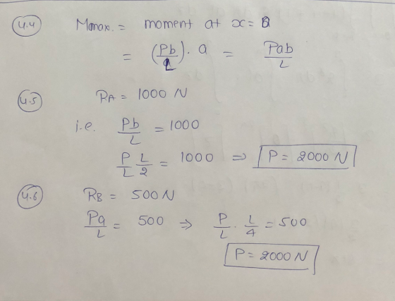
4. (3) A propped beam shown in the Figure supports a concentrated load P. In order...
 4. (3) A propped beam shown in the Figure supports a concentrated load P. In order to make sure the reaction force at support B does not exceed 2 kN, what is the maximum allowable load P? Draw shear force- and bending moment-diagram, find the maximum bending moment. 1.6m-0.8 m --0.8 m Pa2 Pa
 Question 2: A simply supported beam under loading as shown in Figure 1: 1. Draw the influence lines of the bending moment and shear force at point C (L/4) Using the influence lines to determine the bending moment and shear force at section C due to the loading as shown in the figure. 2. 3. There is a distributed live load (w#2.5kN/m) which can vary the location along the beam. Determine the location of the live loads which create the...
 OUESTION 2 The solid cylindrical member in Figure 3 is under a point load of P at point C. If the beam has a radius ofr 50 mm, length L = 4 m, and load P 5 kN and E= 200 GPa (a) Draw the free body, shear force, bending moment and torque diagrams for both sections of the member (4 Marks) (b) What is the maximum bending stress induced in the member? (3 Marks) (c) What is the maximum...
 A simply supported prismatic beam is loaded with a load applied at an angle at point F as shown below The beams connecting points CE and EF can be considered rigid (l-very large). The magnitude of the applied load P is 75kN. NOTE: You must use your student number to calculate the magnitude of the angle, α, and the length EF using the expressions below. The angle, α, is given in degrees and the unit for length EF is m...
 4. A T-shaped cross-sectional beam is loaded as shown in the figure. Determine the following a. Sketch the internal shear force and bending moment diagrams for the beam. b. Calculate the maximum magnitude of the bending stress. Indicate where this occurs on the cross-section and along the length of the beam. c. Calculate the transverse shearing stress at the centroid of the cross-section using the maximum magnitude of the transverse shear force. - 200 mm 8 KN 1.5 kN/m 20...
 3. A simply-supported prismatic long beam KL is pushed upward with P 160 N at point N as illustrated. Please do the followings: (a) Determine the reaction forces at points K and L, respectively including their directions and magnitude and units; (b) Draw the shear diagram (V vs. x) and bending diagram is obtained step-by-step including the mathematical equations of the shear and bending moment curves, and the critical values, transition points, and slopes should be labelled clearly in numerical...
 Calculate the reactions at the supports A, B, and C for the beam in figure 4 and then draw the shear force and bending moment diagrams. At A and B there are simple supports while at C there is a pin joint. If the cross section of the beam is rectangular, with dimensions b-10 mm and h-24 mm what is maximum bending stress in the beam? 12 kN 9 kN/m 22 224m 2
 Problem 5 The cross-sectional area of teh prismatic bar is 0.02 m². If the normal and shear stresses on the plane P are o = 1.25 MPa and to = -1.5 MPa, what are the angle ( and the axial force P. Figure 5
 4. Figure 4 shows a beam with three supports at A, B and D. The
beam also has a pin connection at C. Draw the shear force diagram
and bending moment diagram of the beam. Calculate the maximum
bending stress and maximum shear stress of the beam.
200 mm 5 kN 3 kN/m 30 mm - 25 mm N IITIT 250 mm 3m — 3 m +1.5 m +1.5 m1 30 mm 100 mm Cross-section of beam Figure 4
4. Figure 4 shows a beam with three supports at A, B and D. The
beam also has a pin connection at C. Draw the shear force diagram
and bending moment diagram of the beam. Calculate the maximum
bending stress and maximum shear stress of the beam.
200 mm 5 kN 3 kN/m 30 mm - 25 mm N IITIT 250 mm 3m — 3 m +1.5 m +1.5 m1 30 mm 100 mm Cross-section of beam Figure 4
 a simply supported beam abcd with arectangular cross section
carries the loading shown in figure. the uniform beam has a mass of
33 kg per meter (m kg/m) and a cross section as shown in the
figure. you may take 10 m/s^2 as acceleration.Question A2 A simply supported beam ABCD with a rectangular cross-section carries the loading shown in Figure QA2. The uniform beam has a mass of m kg per meter of length (m kg/m) and a cross-section as shown...
a simply supported beam abcd with arectangular cross section
carries the loading shown in figure. the uniform beam has a mass of
33 kg per meter (m kg/m) and a cross section as shown in the
figure. you may take 10 m/s^2 as acceleration.Question A2 A simply supported beam ABCD with a rectangular cross-section carries the loading shown in Figure QA2. The uniform beam has a mass of m kg per meter of length (m kg/m) and a cross-section as shown...
 4. (3) A propped beam shown in the Figure supports a concentrated load P. In order to make sure the reaction force at support B does not exceed 2 kN, what is the maximum allowable load P? Draw shear force- and bending moment-diagram, find the maximum bending moment. 1.6m-0.8 m --0.8 m Pa2 Pa
Most questions answered within 3 hours.
-
Consider the reaction, C3 H8 + O2 --> CO2 + H2O. How many
moles of O2...
asked 58 minutes ago -
You and your opponent both roll a fair die. If you both roll the
same number,...
asked 1 hour ago -
In a study of the accuracy of fast food drive-through orders,
Restaurant A had 257 accurate...
asked 1 hour ago -
Identify and describe in detail the four categories of
institutions that could be included in a...
asked 1 hour ago -
In python
class Customer:
def __init__(self, customer_id, last_name, first_name, phone_number, address):
self._customer_id = int(customer_id)
self._last_name =...
asked 1 hour ago -
What is an example of a limitation in implementing a new
ERP system and how it...
asked 1 hour ago -
In a section of 9.7cm of an artery with a radius of 2.6mm there
is a...
asked 1 hour ago -
the two carboxylic acid groups of aspartic acid have different
acidities with pKa values of 2.1...
asked 1 hour ago -
Would CuCO3 aqueous salt combined with calcium chloride
form a solid precipitate? If so, what would...
asked 1 hour ago -
How do ECM Solutions assist in embedding a culture of continuous
improvement in an organization? (Project...
asked 1 hour ago -
Directions
These directions introduce the idea of Essential Questions.
Since this may be a new concept...
asked 1 hour ago -
1.b. Fiscal policy is said to suffer from ‘crowding out’.
Explain what this means and why...
asked 2 hours ago