6. (a) Each clock cycle, an input is provided to the finite state machine (FSM) below. Assuming that we start at state 00 and given an input for each tick, fill in the table to show the next state.
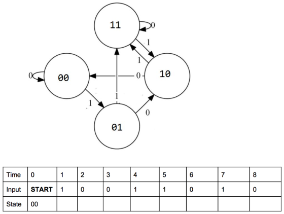
(b) What bit sequence(s) does this FSM recognize? Your answer should be a string of bits (ex. “01” or “1110”).
Homework Answers
a)
| 0 | 0 | 1 | 2 | 3 | 4 | 5 | 6 | 7 | 8 |
| Input | Start | 1 | 0 | 0 | 1 | 1 | 0 | 1 | 0 |
| State | 00 | 01 | 10 | 00 | 01 | 11 | 11 | 10 | 00 |
b) Since there are no final state marked in the FSM, hence it does not recognises any string
Add Answer to:
6. (a) Each clock cycle, an input is provided to the finite
state machine (FSM) below....
Design the following finite state machine (FSM). It has two 1-bit inputs (in1 and in2) and...
Design the following finite state machine (FSM). It has two 1-bit inputs (in1 and in2) and two 1-bit outputs (out1 and out2). The first output (out1) bit should be equal to one if, on both of the last two cycles, in1 and in2 were EQUAL to each other; otherwise, out1 should equal zero. The second output (out2) should be equal to 1 if, on the last cycle, in1 and in2 were NOT EQUAL to each other; otherwise, out2 should equal...
Table Q4.1 shows the state transition table for a finite state machine (FSM) with one input...
 Table Q4.1 shows the state transition table for a finite state
machine (FSM) with one input x, one output z and eight states.
(a) Copy the table of Table Q4.2 into your examination book and
determine the states and outputs for the input listed, assuming a
start current state of ‘1’. Determine what function the FSM is
performing.
(b) Using the implication chart method, determine the minimal
number of states. Show clearly your analysis.
(c) Draw the reduced state transition...
Table Q4.1 shows the state transition table for a finite state
machine (FSM) with one input x, one output z and eight states.
(a) Copy the table of Table Q4.2 into your examination book and
determine the states and outputs for the input listed, assuming a
start current state of ‘1’. Determine what function the FSM is
performing.
(b) Using the implication chart method, determine the minimal
number of states. Show clearly your analysis.
(c) Draw the reduced state transition...
0/3 D6.15 Write an assembly main program that implements this Mealy finite state machine. happy The FSM state graph...
 0/3 D6.15 Write an assembly main program that implements this Mealy finite state machine. happy The FSM state graph, shown below, is givenP and cannot be changed. The input is on Port A bit 0 and the output is on Port B bits 3,2,1,0. There are three states (happy, hungry, sleepy), and initial state is happy. hungry 1/8 1/2 143 0/4 sleepy a) Show the ROM-based FSM data structure b) Show the initialization and controller software. Initialize the direction registers,...
3. Finite State Machine. Using a ROM based finite state machine (FSM), design a bi-directional repetitive...
 3. Finite State Machine. Using a ROM based finite state machine (FSM), design a bi-directional repetitive 3-bit modulo-6 (0,1,2,3,4,5) counter (see Table 3). The design has one input named Dir and three outputs named B2, B1 and BO. The outputs (B2, B1 and BO) are dependent upon being in the present state only. After each clock pulse, when Dir is at logic "O', the outputs (B2, B1, BO) step through the count sequence in following order:- 0,1,2,3,4,5. After each clock...
Design a finite state machine that recognizes the input string "k", "klm", and "mkl" by outputing...
Design a finite state machine that recognizes the input string "k", "klm", and "mkl" by outputing a "1" (otherwise output "0" for the input). the input alphabet is {k, l, m}. the output alphabet is {0,1} i) Draw the FSM ii) Create the state transition table iii) what is the sequence of states for kkkllmklmkmmkm
a) A synchronous finite state machine (FSM) is described by the state table in Fig. 3. Show how redundant states may...
 a) A synchronous finite state machine (FSM) is described by the state table in Fig. 3. Show how redundant states may be found and eliminated to minimise this FSM. [15 marks) b) Derive Boolean equations for the implementation of the reduced FSM. (15 marks] Next state Output Current X1Xo state 00 01 11 10 Z1Zo A A F E C 00 B C B A 01 F A B C 00 G DİACİ 10 Figure 3 Tum over...
a) A...
a) A synchronous finite state machine (FSM) is described by the state table in Fig. 3. Show how redundant states may be found and eliminated to minimise this FSM. [15 marks) b) Derive Boolean equations for the implementation of the reduced FSM. (15 marks] Next state Output Current X1Xo state 00 01 11 10 Z1Zo A A F E C 00 B C B A 01 F A B C 00 G DİACİ 10 Figure 3 Tum over...
a) A...
4. Construct a finite-state machine that changes every other bit, starting with the second bit, of...
 4. Construct a finite-state machine that changes every other bit, starting with the second bit, of an input string, and leaves the other bits unchanged. (Show as a diagram.) 5. Construct a finite-state machine that accepts bit strings that contain at least 3 consecutive 1's. 6. Construct a finite-state machine that accepts bit strings that do not contain any 3 consecutive l's
4. Construct a finite-state machine that changes every other bit, starting with the second bit, of an input...
4. Construct a finite-state machine that changes every other bit, starting with the second bit, of an input string, and leaves the other bits unchanged. (Show as a diagram.) 5. Construct a finite-state machine that accepts bit strings that contain at least 3 consecutive 1's. 6. Construct a finite-state machine that accepts bit strings that do not contain any 3 consecutive l's
4. Construct a finite-state machine that changes every other bit, starting with the second bit, of an input...
Question 2 Provide solution for Question 2 and explain reasoning in detail a) Develop a Finite...
 Question 2 Provide solution for Question 2 and explain reasoning in detail a) Develop a Finite State Machine (FSM) that recognize the pattern "11" or "110" within a sequence of bits that are read in series. When we recognize the pattern, we assign the output R to 1. Here is an illustration of the desired behavior. R. 0 TempsI b) Consider the following FSM 01 reset 00+01+10 00+11+10 1) Give the transition state table and the output table (if necessary)...
Write assembly or C software to implement the following Mealy FSM (Figure 2.42). Include the FSM state machine, port ini...
 Write assembly or C software to implement the following Mealy
FSM (Figure 2.42). Include the FSM state machine, port
initialization, timer initialization, and the FSM controller. The
command sequence will be input, output, wait 10 ms, input, then
branch to next state. The 1-bit input is on Port P (PP0), and the
3-bit output is on Port P (PP3, PP2, PP1). Assume the E clock is 8
MHz. Microcontroller MC9S12
0/4 Happy Hungry 1/2 1/5 1/3 06 Sleepy Figure 2.42...
Write assembly or C software to implement the following Mealy
FSM (Figure 2.42). Include the FSM state machine, port
initialization, timer initialization, and the FSM controller. The
command sequence will be input, output, wait 10 ms, input, then
branch to next state. The 1-bit input is on Port P (PP0), and the
3-bit output is on Port P (PP3, PP2, PP1). Assume the E clock is 8
MHz. Microcontroller MC9S12
0/4 Happy Hungry 1/2 1/5 1/3 06 Sleepy Figure 2.42...
Design a finite state machine with an input u. The state diagram do the FSM is...
 Design a finite state machine with an input u. The
state diagram do the FSM is given in the diagram below. Use only
D-Flipflops and NAND gates for your design.
So Sg s, s, s,
Design a finite state machine with an input u. The
state diagram do the FSM is given in the diagram below. Use only
D-Flipflops and NAND gates for your design.
So Sg s, s, s,
 Table Q4.1 shows the state transition table for a finite state
machine (FSM) with one input x, one output z and eight states.
(a) Copy the table of Table Q4.2 into your examination book and
determine the states and outputs for the input listed, assuming a
start current state of ‘1’. Determine what function the FSM is
performing.
(b) Using the implication chart method, determine the minimal
number of states. Show clearly your analysis.
(c) Draw the reduced state transition...
Table Q4.1 shows the state transition table for a finite state
machine (FSM) with one input x, one output z and eight states.
(a) Copy the table of Table Q4.2 into your examination book and
determine the states and outputs for the input listed, assuming a
start current state of ‘1’. Determine what function the FSM is
performing.
(b) Using the implication chart method, determine the minimal
number of states. Show clearly your analysis.
(c) Draw the reduced state transition...
 0/3 D6.15 Write an assembly main program that implements this Mealy finite state machine. happy The FSM state graph, shown below, is givenP and cannot be changed. The input is on Port A bit 0 and the output is on Port B bits 3,2,1,0. There are three states (happy, hungry, sleepy), and initial state is happy. hungry 1/8 1/2 143 0/4 sleepy a) Show the ROM-based FSM data structure b) Show the initialization and controller software. Initialize the direction registers,...
 3. Finite State Machine. Using a ROM based finite state machine (FSM), design a bi-directional repetitive 3-bit modulo-6 (0,1,2,3,4,5) counter (see Table 3). The design has one input named Dir and three outputs named B2, B1 and BO. The outputs (B2, B1 and BO) are dependent upon being in the present state only. After each clock pulse, when Dir is at logic "O', the outputs (B2, B1, BO) step through the count sequence in following order:- 0,1,2,3,4,5. After each clock...
 a) A synchronous finite state machine (FSM) is described by the state table in Fig. 3. Show how redundant states may be found and eliminated to minimise this FSM. [15 marks) b) Derive Boolean equations for the implementation of the reduced FSM. (15 marks] Next state Output Current X1Xo state 00 01 11 10 Z1Zo A A F E C 00 B C B A 01 F A B C 00 G DİACİ 10 Figure 3 Tum over...
a) A...
a) A synchronous finite state machine (FSM) is described by the state table in Fig. 3. Show how redundant states may be found and eliminated to minimise this FSM. [15 marks) b) Derive Boolean equations for the implementation of the reduced FSM. (15 marks] Next state Output Current X1Xo state 00 01 11 10 Z1Zo A A F E C 00 B C B A 01 F A B C 00 G DİACİ 10 Figure 3 Tum over...
a) A...
 4. Construct a finite-state machine that changes every other bit, starting with the second bit, of an input string, and leaves the other bits unchanged. (Show as a diagram.) 5. Construct a finite-state machine that accepts bit strings that contain at least 3 consecutive 1's. 6. Construct a finite-state machine that accepts bit strings that do not contain any 3 consecutive l's
4. Construct a finite-state machine that changes every other bit, starting with the second bit, of an input...
4. Construct a finite-state machine that changes every other bit, starting with the second bit, of an input string, and leaves the other bits unchanged. (Show as a diagram.) 5. Construct a finite-state machine that accepts bit strings that contain at least 3 consecutive 1's. 6. Construct a finite-state machine that accepts bit strings that do not contain any 3 consecutive l's
4. Construct a finite-state machine that changes every other bit, starting with the second bit, of an input...
 Question 2 Provide solution for Question 2 and explain reasoning in detail a) Develop a Finite State Machine (FSM) that recognize the pattern "11" or "110" within a sequence of bits that are read in series. When we recognize the pattern, we assign the output R to 1. Here is an illustration of the desired behavior. R. 0 TempsI b) Consider the following FSM 01 reset 00+01+10 00+11+10 1) Give the transition state table and the output table (if necessary)...
 Write assembly or C software to implement the following Mealy
FSM (Figure 2.42). Include the FSM state machine, port
initialization, timer initialization, and the FSM controller. The
command sequence will be input, output, wait 10 ms, input, then
branch to next state. The 1-bit input is on Port P (PP0), and the
3-bit output is on Port P (PP3, PP2, PP1). Assume the E clock is 8
MHz. Microcontroller MC9S12
0/4 Happy Hungry 1/2 1/5 1/3 06 Sleepy Figure 2.42...
Write assembly or C software to implement the following Mealy
FSM (Figure 2.42). Include the FSM state machine, port
initialization, timer initialization, and the FSM controller. The
command sequence will be input, output, wait 10 ms, input, then
branch to next state. The 1-bit input is on Port P (PP0), and the
3-bit output is on Port P (PP3, PP2, PP1). Assume the E clock is 8
MHz. Microcontroller MC9S12
0/4 Happy Hungry 1/2 1/5 1/3 06 Sleepy Figure 2.42...
 Design a finite state machine with an input u. The
state diagram do the FSM is given in the diagram below. Use only
D-Flipflops and NAND gates for your design.
So Sg s, s, s,
Design a finite state machine with an input u. The
state diagram do the FSM is given in the diagram below. Use only
D-Flipflops and NAND gates for your design.
So Sg s, s, s,
Most questions answered within 3 hours.
-
What are John’s potential claims if he is terminated
this week?
John is a 54-year-old man...
asked 8 minutes ago -
A (8.5) cm tall object is placed at a distance of (14.2) cm from
a convex...
asked 17 minutes ago -
(2) For the following questions, consider a data set that
exhibits a normal distribution. Report the...
asked 18 minutes ago -
What exactly is an information system? How does it work" What
are its people organization,
...
asked 19 minutes ago -
The Food Marketing Institute shows that 17% of households spend
more than $100 per week on...
asked 29 minutes ago -
Go to NCBI BLAST search web page
1st search: GEKDLRRAKDINQEVYNF
2nd search: PTSQRLQLLEPFDK
3rd search: GEKDLRRAKDINQEVYNF...
asked 32 minutes ago -
Explain how each of the following three conditions could be a
red flag for a register...
asked 37 minutes ago -
In a two-way factorial ANOVA, the final F-ratio for
factor AxB is determined by dividing _____...
asked 1 hour ago -
Show your solutions for answer.
4. An aqueous solution contains 9.21 g of
K4Fe(CN)6 in a...
asked 37 minutes ago -
The random variable X has a uniform distribution with values
between 16 and 18. What is...
asked 47 minutes ago -
Evaluate each of the following transactions in terms of their
effect on assets, liabilities, and equity....
asked 46 minutes ago -
The amounts of nicotine in a certain brand of cigarette are
normally distributed with a mean...
asked 1 hour ago