
Homework Answers

Add Answer to:
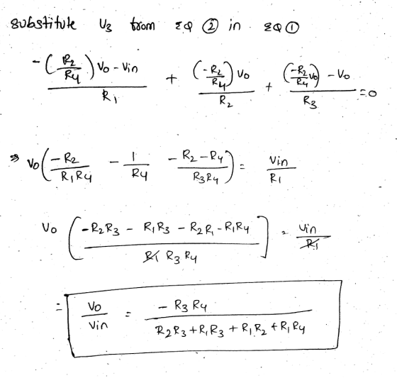
Figure 1 Q 3. For the circuit in figure 2 find Vo/V. (25 Points) R, 2...
Q1. The values of the difference amplifier in figure 1 are Ao 5x 10⁵, Rı =...
 Q1. The values of the difference amplifier in figure 1 are Ao 5x 10⁵, Rı = 5kQ, RF = 50M, Ra-2kQ, and Rx-20kS2. The input voltages are vb-5mV and Va--15mV. Find the out voltage vo. (5 Points) RF R1 Figure 1 Q2. Design an integrator as shown in figure 2 to be operated with an AC signal of 5 kHz and to give a closed loop voltage gain of Af-10 at w=1 rad/s. (5 Points) iRF RI 79 +Vcc 2...
Problem 1 (25 points) Design a diode clamper circuit to generate the output Vo given the...
 Problem 1 (25 points) Design a diode clamper circuit to generate the output Vo given the input signal Vi as shown in the figure below: VI Vo A 35 10 5 -20 Design the circuit for two cases: a) (15 points) Vy -0 b) (10 points) V,0.7 V
Design a band pass filter (BPF) with a circuit shown below (ie find R, R, RF,...
 Design a band pass filter (BPF) with a circuit shown below (ie find R, R, RF, RF) Assume: fi2 kHz f=100 Hz A.A 2 (the overall gain) Ci=0.01 uF Cl'-05pF R1-R1 - 10 K I R C1 Vi R Vo RF RF R1 R1 1 Hint: J2TRC
Design a band pass filter (BPF) with a circuit shown below (ie find R, R, RF, RF) Assume: fi2 kHz f=100 Hz A.A 2 (the overall gain) Ci=0.01 uF Cl'-05pF R1-R1 - 10...
Design a band pass filter (BPF) with a circuit shown below (ie find R, R, RF, RF) Assume: fi2 kHz f=100 Hz A.A 2 (the overall gain) Ci=0.01 uF Cl'-05pF R1-R1 - 10 K I R C1 Vi R Vo RF RF R1 R1 1 Hint: J2TRC
Design a band pass filter (BPF) with a circuit shown below (ie find R, R, RF, RF) Assume: fi2 kHz f=100 Hz A.A 2 (the overall gain) Ci=0.01 uF Cl'-05pF R1-R1 - 10...
The circuit shown in Figure Q4-1 includes an audio source and the equivalent circuit of a...
 The circuit shown in Figure Q4-1 includes an audio source and the equivalent circuit of a loudspeaker that you have been asked to analyse. 4. a) Assuming the speaker is to operate at a single frequency of 200 Hz and is5 driven by a cosinusoidal signal with peak amplitude of 20 V; determine the equivalent impedance of the speaker When connected to the audio source, calculate the current flow i() When testing the loudspeaker detailed in Q4a) i), you can...
Problem 3 (30 points): For the circuit in Fig. 3, v, has an RMS value of...
 Problem 3 (30 points): For the circuit in Fig. 3, v, has an RMS value of 9.0 V and a frequency of 60 Hz. Assume that R-20 Ω and that V,-0.7 V for each diode. Vs R o Figure 3: Circuit for Problem 3 (10 points) 1. Find the maximum value of Vo 2. Find the value of C to guarantee a ripple voltage of 0.25 V or less. (10 points) 3. For what fraction of the time is the...
ONLY NEED HELP WITH C AND D PLEASE! The differentiator circuit shown in Figure 1 uses an op-amp with ideal characteristics C1 Figure 1 (a) Prove that the gain of the circuit is given by the following...
 ONLY NEED HELP WITH C AND D PLEASE!
The differentiator circuit shown in Figure 1 uses an op-amp with ideal characteristics C1 Figure 1 (a) Prove that the gain of the circuit is given by the following expression using first principles for an ideal op-amp (2 marks) Gain = - (1 + juli R 1) (b) If the differentiator frequency (at unity gain) is 100Hz and the high frequency gain is 40dB and R2 is 220kQ, design the rest of...
ONLY NEED HELP WITH C AND D PLEASE!
The differentiator circuit shown in Figure 1 uses an op-amp with ideal characteristics C1 Figure 1 (a) Prove that the gain of the circuit is given by the following expression using first principles for an ideal op-amp (2 marks) Gain = - (1 + juli R 1) (b) If the differentiator frequency (at unity gain) is 100Hz and the high frequency gain is 40dB and R2 is 220kQ, design the rest of...
2. H(s)Vo/v, for the circuit shown in Figure P9-12. 1 ΜΩ Figure P9-12 2. H(s)Vo/v, for the circuit shown in Figure P9-12. 1 ΜΩ Figure P9-12
 2. H(s)Vo/v, for the circuit shown in Figure P9-12. 1 ΜΩ Figure P9-12
2. H(s)Vo/v, for the circuit shown in Figure P9-12. 1 ΜΩ Figure P9-12
2. H(s)Vo/v, for the circuit shown in Figure P9-12. 1 ΜΩ Figure P9-12
need help with C and D please The differentiator circuit shown in Figure 1 uses an op-amp with ideal characteristics. R2 R1 C1 Vi O Figure 1 (c) Sketch the Bode magnitude response for this circ...
 need help with C and D please
The differentiator circuit shown in Figure 1 uses an op-amp with ideal characteristics. R2 R1 C1 Vi O Figure 1 (c) Sketch the Bode magnitude response for this circuit for the frequency range of 10° to 108 Hz. (7 marks) (d) Sketch the output waveform of the differentiator and justify your answer, if v is as shown in Figure 2 with a period of: () 100 ms (ii) 10 us (6 marks) 0.11...
need help with C and D please
The differentiator circuit shown in Figure 1 uses an op-amp with ideal characteristics. R2 R1 C1 Vi O Figure 1 (c) Sketch the Bode magnitude response for this circuit for the frequency range of 10° to 108 Hz. (7 marks) (d) Sketch the output waveform of the differentiator and justify your answer, if v is as shown in Figure 2 with a period of: () 100 ms (ii) 10 us (6 marks) 0.11...
14. Problem For the circuit in figure below, find the steady-state output voltage vo (t). The inp...
 14. Problem For the circuit in figure below, find the steady-state output voltage vo (t). The input signal is v (t) and C = 5 μF 4-2 cos 100t, R 1 kΩ Do C R 12 U)
14. Problem For the circuit in figure below, find the steady-state output voltage vo (t). The input signal is v (t) and C = 5 μF 4-2 cos 100t, R 1 kΩ Do C R 12 U)
14. Problem For the circuit in figure below, find the steady-state output voltage vo (t). The input signal is v (t) and C = 5 μF 4-2 cos 100t, R 1 kΩ Do C R 12 U)
In the voltage-divider circuit shown in the figure, the no-load value of vo is 5 V...
 In the voltage-divider circuit shown in the figure, the no-load value of vo is 5 V When the load resistance RI is attached across the terminals a and b, vo drops to 3 V.(Figure 1) PartA Find RL Express your answer with the appropriate units RI-7.28 Submit Previous Answers Request Answer Incorrect, Try Again: One attempt remaining Provide Feedback igure 1 of 1 40Ω 20 V R2 vo
 Q1. The values of the difference amplifier in figure 1 are Ao 5x 10⁵, Rı = 5kQ, RF = 50M, Ra-2kQ, and Rx-20kS2. The input voltages are vb-5mV and Va--15mV. Find the out voltage vo. (5 Points) RF R1 Figure 1 Q2. Design an integrator as shown in figure 2 to be operated with an AC signal of 5 kHz and to give a closed loop voltage gain of Af-10 at w=1 rad/s. (5 Points) iRF RI 79 +Vcc 2...
 Problem 1 (25 points) Design a diode clamper circuit to generate the output Vo given the input signal Vi as shown in the figure below: VI Vo A 35 10 5 -20 Design the circuit for two cases: a) (15 points) Vy -0 b) (10 points) V,0.7 V
 Design a band pass filter (BPF) with a circuit shown below (ie find R, R, RF, RF) Assume: fi2 kHz f=100 Hz A.A 2 (the overall gain) Ci=0.01 uF Cl'-05pF R1-R1 - 10 K I R C1 Vi R Vo RF RF R1 R1 1 Hint: J2TRC
Design a band pass filter (BPF) with a circuit shown below (ie find R, R, RF, RF) Assume: fi2 kHz f=100 Hz A.A 2 (the overall gain) Ci=0.01 uF Cl'-05pF R1-R1 - 10...
Design a band pass filter (BPF) with a circuit shown below (ie find R, R, RF, RF) Assume: fi2 kHz f=100 Hz A.A 2 (the overall gain) Ci=0.01 uF Cl'-05pF R1-R1 - 10 K I R C1 Vi R Vo RF RF R1 R1 1 Hint: J2TRC
Design a band pass filter (BPF) with a circuit shown below (ie find R, R, RF, RF) Assume: fi2 kHz f=100 Hz A.A 2 (the overall gain) Ci=0.01 uF Cl'-05pF R1-R1 - 10...
 The circuit shown in Figure Q4-1 includes an audio source and the equivalent circuit of a loudspeaker that you have been asked to analyse. 4. a) Assuming the speaker is to operate at a single frequency of 200 Hz and is5 driven by a cosinusoidal signal with peak amplitude of 20 V; determine the equivalent impedance of the speaker When connected to the audio source, calculate the current flow i() When testing the loudspeaker detailed in Q4a) i), you can...
 Problem 3 (30 points): For the circuit in Fig. 3, v, has an RMS value of 9.0 V and a frequency of 60 Hz. Assume that R-20 Ω and that V,-0.7 V for each diode. Vs R o Figure 3: Circuit for Problem 3 (10 points) 1. Find the maximum value of Vo 2. Find the value of C to guarantee a ripple voltage of 0.25 V or less. (10 points) 3. For what fraction of the time is the...
 ONLY NEED HELP WITH C AND D PLEASE!
The differentiator circuit shown in Figure 1 uses an op-amp with ideal characteristics C1 Figure 1 (a) Prove that the gain of the circuit is given by the following expression using first principles for an ideal op-amp (2 marks) Gain = - (1 + juli R 1) (b) If the differentiator frequency (at unity gain) is 100Hz and the high frequency gain is 40dB and R2 is 220kQ, design the rest of...
ONLY NEED HELP WITH C AND D PLEASE!
The differentiator circuit shown in Figure 1 uses an op-amp with ideal characteristics C1 Figure 1 (a) Prove that the gain of the circuit is given by the following expression using first principles for an ideal op-amp (2 marks) Gain = - (1 + juli R 1) (b) If the differentiator frequency (at unity gain) is 100Hz and the high frequency gain is 40dB and R2 is 220kQ, design the rest of...
 2. H(s)Vo/v, for the circuit shown in Figure P9-12. 1 ΜΩ Figure P9-12
2. H(s)Vo/v, for the circuit shown in Figure P9-12. 1 ΜΩ Figure P9-12
2. H(s)Vo/v, for the circuit shown in Figure P9-12. 1 ΜΩ Figure P9-12
 need help with C and D please
The differentiator circuit shown in Figure 1 uses an op-amp with ideal characteristics. R2 R1 C1 Vi O Figure 1 (c) Sketch the Bode magnitude response for this circuit for the frequency range of 10° to 108 Hz. (7 marks) (d) Sketch the output waveform of the differentiator and justify your answer, if v is as shown in Figure 2 with a period of: () 100 ms (ii) 10 us (6 marks) 0.11...
need help with C and D please
The differentiator circuit shown in Figure 1 uses an op-amp with ideal characteristics. R2 R1 C1 Vi O Figure 1 (c) Sketch the Bode magnitude response for this circuit for the frequency range of 10° to 108 Hz. (7 marks) (d) Sketch the output waveform of the differentiator and justify your answer, if v is as shown in Figure 2 with a period of: () 100 ms (ii) 10 us (6 marks) 0.11...
 14. Problem For the circuit in figure below, find the steady-state output voltage vo (t). The input signal is v (t) and C = 5 μF 4-2 cos 100t, R 1 kΩ Do C R 12 U)
14. Problem For the circuit in figure below, find the steady-state output voltage vo (t). The input signal is v (t) and C = 5 μF 4-2 cos 100t, R 1 kΩ Do C R 12 U)
14. Problem For the circuit in figure below, find the steady-state output voltage vo (t). The input signal is v (t) and C = 5 μF 4-2 cos 100t, R 1 kΩ Do C R 12 U)
 In the voltage-divider circuit shown in the figure, the no-load value of vo is 5 V When the load resistance RI is attached across the terminals a and b, vo drops to 3 V.(Figure 1) PartA Find RL Express your answer with the appropriate units RI-7.28 Submit Previous Answers Request Answer Incorrect, Try Again: One attempt remaining Provide Feedback igure 1 of 1 40Ω 20 V R2 vo
Most questions answered within 3 hours.
-
Write a program to solve the Josephus problem, with the following
modification:
Sample Input:
./a.out n...
asked 2 minutes ago -
At the start of a CD it is spinning at a rate of 525 rpm
(revolutions...
asked 38 minutes ago -
4. Without doing any calculations, predict whether the observed
∆T would increase, decrease or remain the...
asked 1 hour ago -
Based on the range, which of the following sets of scores has
the greatest variability? 3,...
asked 3 hours ago -
Ripples in a pond travel at a velocity of 3 m/s with one peak
passing a...
asked 2 hours ago -
A man stands on the roof of a building of height 13.0 mm and
throws a...
asked 2 hours ago -
The extent to which assets are financed by borrowed funds and
other liabilities is indicated by:...
asked 3 hours ago -
Explain in detail
Germany is the fifth largest economy
explain what goods and services Germany specializes...
asked 4 hours ago -
The density of platinum is 21.45 g/mL. If a cube of platinum
with a mass of...
asked 4 hours ago -
Accounts Receivable
Sales
A/R Posting
Extended Sales Invoice
Packing Slip
Compare invoice to packing slip 2...
asked 4 hours ago -
Michaella, age 23, is a full-time law student and is claimed by
her parents as a...
asked 4 hours ago -
Why are polymers not typically casted into products?
asked 4 hours ago