
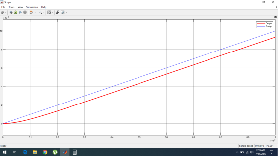
For the system shown here in tasks 1-4 I have determined that for the value of K<3 the system is unstable, for K=3 the system is in oscillation and K>3 the system is stable. However i am unsure how to calculate the value of K to achieve a steady state error of 0.01% for T ≥ 10.
Many Thanks for the assistance
Homework Answers
General Formula to find Steady-State Error:

Let our input is impulse:


We are given that, the steady-state error is less than 0.01%.


Response to a ramp input:
Add Answer to:
For the system shown here in tasks 1-4 I have determined that
for the value of...
Question 2 Consider the system shown in Figure Q2, where Wis a unit step disturbance and R is a unit step input. 0.4 s+ 1 10 Figure Q2 (5 marks) (3 marks) (c) Find the value for K so that the steady...
 Question 2 Consider the system shown in Figure Q2, where Wis a unit step disturbance and R is a unit step input. 0.4 s+ 1 10 Figure Q2 (5 marks) (3 marks) (c) Find the value for K so that the steady state error due to w(t) is less than 0.01; 6 marks) (d) In order to eliminate the steady state error, show whether a PI controller can be successful 6 marks) (a) Find the expression of E(s)-R(s)-Y(s) in terms...
Question 4: Consider the following system: 0.01 a) Describe the response to a unit step input...
 Question 4: Consider the following system: 0.01 a) Describe the response to a unit step input for K 0.01 and K-0.1 and determine the value of K for a non-oscillatory minimum response time. b) If we let K-1, what will be the value of the steady state error of this system in response to a unit step input? c) If we now replace the "proportional controller" (the box with the K in it) with a proportional integral (PI) controller, with...
PROBLEM 4 Suppose that a system is shown in Figure 4. There are three controllers that might be incorporated into this system. 1. Ge (s)-K (proportional (P) controller) 2. GS)K/s (integral (I) contro...
 PROBLEM 4 Suppose that a system is shown in Figure 4. There are three controllers that might be incorporated into this system. 1. Ge (s)-K (proportional (P) controller) 2. GS)K/s (integral (I) controller) 3. G (s)K(1+1/s) (proportional, integral (PI) controller) The system requirements are T, < 10 seconds and P0 10% for a unit step response. (a) For the (P) controller, write a piece of MATLAB code to plot root locus for 0<K<,and find the K value so that the...
Problem #7 (10 points) For the feedback control system shown in figure (4), R) I. 2....
 Problem #7 (10 points) For the feedback control system shown in figure (4), R) I. 2. Determine the steady state error ess when K = 1 Determine the value of K to minimize the steady state error ess R(S) (s +2) 6+5 Figure (4) Problem #8 (10 points) For the feedback control system shown in figure (5, R(s)-ine the range of K such that the absolute value of the steady state error is less than 0.1 R(S) s+K Y(S) Figure...
1. A feedback control system is shown in the figure below. Suppose that our design objective...
 1. A feedback control system is shown in the figure below. Suppose that our design objective is to find a controller Gc(S) of minimal complexity such that our closed-loop system can track a unit step input with a steady-state error of zero. (b) Now consider a more complex controller Gc(S) = [ Ko + K//s] where Ko = 2 and Ki = 20. (This is a proportional + integral (PI) controller). Plot the unit step response, and determine the steady-state...
Problem 4. Consider the control system shown below with plant G(s) that has time con- stants...
 Problem 4. Consider the control system shown below with plant G(s) that has time con- stants T1 = 2, T2 = 10, and gain k = 0.1. 4 673 +1679+1) (1.) Sketch the pole-zero plot for G(s). Is one of the poles more dominant? Using MATLAB, simulate the step response of the plant itself, along with G1(s) and G2(s) as defined by Gl(s) = and G2(s) = sti + 1 ST2+1 (2.) Design a proportional gain C(s) = K so...
A unity feedback closed loop control system is displayed in Figure 4. (a) Assume that the control...
 Please solve as a MATLAB code.
A unity feedback closed loop control system is displayed in Figure 4. (a) Assume that the controller is given by G (s) 2. Based on the lsim function of MATLAB, calculate and obtain the graph of the response for (t) at. Here a 0.5°/s. Find the height error after 10 seconds, (b) In order to reduce the steady-state error, substitute G (s) with the following controller This is a Proportional-Integral (PI) controller. Repeat part...
Please solve as a MATLAB code.
A unity feedback closed loop control system is displayed in Figure 4. (a) Assume that the controller is given by G (s) 2. Based on the lsim function of MATLAB, calculate and obtain the graph of the response for (t) at. Here a 0.5°/s. Find the height error after 10 seconds, (b) In order to reduce the steady-state error, substitute G (s) with the following controller This is a Proportional-Integral (PI) controller. Repeat part...
Question 3 (10 +10+10+15 45 marks) E(s) C(s) R(s) Figure 3: Unity feedback control system for Question 3 For the unity...
 Question 3 (10 +10+10+15 45 marks) E(s) C(s) R(s) Figure 3: Unity feedback control system for Question 3 For the unity feedback control system shown in Figure 3, 100 G(S) (s+2)(+10) Page 3 of 7 NEE3201 Examination Paper CRICOS Provider No: 00124k a) Determine the phase margin, the gain crossover frequency, the gain margin, the phase crossover frequency of the system when Gc(s)-1, 10 marks) b) Design a proportional controller Gc(s)-K so that a phase margin of 50° is achieved....
Elevator motors require feedback control to avoid speed differences between up- ward and downward movement and...
 Elevator motors require feedback control to avoid speed differences between up- ward and downward movement and when a different number of passengers ride the elevator car. Soft acceleration and deceleration is achieved with the same feedback control system. A possible feedback control system is shown in Figure 2. E(s) Motor R(S) H(S) w(S) S+5 10 S+10 Figure 2: motor. Suggested feedback control system for controlling the speed ?(s) of an elevator The motor speed is measured with an optical encoder,...
 Question 2 Consider the system shown in Figure Q2, where Wis a unit step disturbance and R is a unit step input. 0.4 s+ 1 10 Figure Q2 (5 marks) (3 marks) (c) Find the value for K so that the steady state error due to w(t) is less than 0.01; 6 marks) (d) In order to eliminate the steady state error, show whether a PI controller can be successful 6 marks) (a) Find the expression of E(s)-R(s)-Y(s) in terms...
 Question 2 Consider the system shown in Figure Q2, where Wis a unit step disturbance and R is a unit step input. 0.4 s+ 1 10 Figure Q2 (5 marks) (3 marks) (c) Find the value for K so that the steady state error due to w(t) is less than 0.01; 6 marks) (d) In order to eliminate the steady state error, show whether a PI controller can be successful 6 marks) (a) Find the expression of E(s)-R(s)-Y(s) in terms...
 Question 4: Consider the following system: 0.01 a) Describe the response to a unit step input for K 0.01 and K-0.1 and determine the value of K for a non-oscillatory minimum response time. b) If we let K-1, what will be the value of the steady state error of this system in response to a unit step input? c) If we now replace the "proportional controller" (the box with the K in it) with a proportional integral (PI) controller, with...
 PROBLEM 4 Suppose that a system is shown in Figure 4. There are three controllers that might be incorporated into this system. 1. Ge (s)-K (proportional (P) controller) 2. GS)K/s (integral (I) controller) 3. G (s)K(1+1/s) (proportional, integral (PI) controller) The system requirements are T, < 10 seconds and P0 10% for a unit step response. (a) For the (P) controller, write a piece of MATLAB code to plot root locus for 0<K<,and find the K value so that the...
 Problem #7 (10 points) For the feedback control system shown in figure (4), R) I. 2. Determine the steady state error ess when K = 1 Determine the value of K to minimize the steady state error ess R(S) (s +2) 6+5 Figure (4) Problem #8 (10 points) For the feedback control system shown in figure (5, R(s)-ine the range of K such that the absolute value of the steady state error is less than 0.1 R(S) s+K Y(S) Figure...
 1. A feedback control system is shown in the figure below. Suppose that our design objective is to find a controller Gc(S) of minimal complexity such that our closed-loop system can track a unit step input with a steady-state error of zero. (b) Now consider a more complex controller Gc(S) = [ Ko + K//s] where Ko = 2 and Ki = 20. (This is a proportional + integral (PI) controller). Plot the unit step response, and determine the steady-state...
 Problem 4. Consider the control system shown below with plant G(s) that has time con- stants T1 = 2, T2 = 10, and gain k = 0.1. 4 673 +1679+1) (1.) Sketch the pole-zero plot for G(s). Is one of the poles more dominant? Using MATLAB, simulate the step response of the plant itself, along with G1(s) and G2(s) as defined by Gl(s) = and G2(s) = sti + 1 ST2+1 (2.) Design a proportional gain C(s) = K so...
 Please solve as a MATLAB code.
A unity feedback closed loop control system is displayed in Figure 4. (a) Assume that the controller is given by G (s) 2. Based on the lsim function of MATLAB, calculate and obtain the graph of the response for (t) at. Here a 0.5°/s. Find the height error after 10 seconds, (b) In order to reduce the steady-state error, substitute G (s) with the following controller This is a Proportional-Integral (PI) controller. Repeat part...
Please solve as a MATLAB code.
A unity feedback closed loop control system is displayed in Figure 4. (a) Assume that the controller is given by G (s) 2. Based on the lsim function of MATLAB, calculate and obtain the graph of the response for (t) at. Here a 0.5°/s. Find the height error after 10 seconds, (b) In order to reduce the steady-state error, substitute G (s) with the following controller This is a Proportional-Integral (PI) controller. Repeat part...
 Question 3 (10 +10+10+15 45 marks) E(s) C(s) R(s) Figure 3: Unity feedback control system for Question 3 For the unity feedback control system shown in Figure 3, 100 G(S) (s+2)(+10) Page 3 of 7 NEE3201 Examination Paper CRICOS Provider No: 00124k a) Determine the phase margin, the gain crossover frequency, the gain margin, the phase crossover frequency of the system when Gc(s)-1, 10 marks) b) Design a proportional controller Gc(s)-K so that a phase margin of 50° is achieved....
 Elevator motors require feedback control to avoid speed differences between up- ward and downward movement and when a different number of passengers ride the elevator car. Soft acceleration and deceleration is achieved with the same feedback control system. A possible feedback control system is shown in Figure 2. E(s) Motor R(S) H(S) w(S) S+5 10 S+10 Figure 2: motor. Suggested feedback control system for controlling the speed ?(s) of an elevator The motor speed is measured with an optical encoder,...
Most questions answered within 3 hours.
-
Blood pressure is normally taken on the upper arm at the level
of the heart. Suppose,...
asked 1 minute ago -
trust is best established through the combination of ------and
------- .
1. magnanimity and justice
2....
asked 2 minutes ago -
Calculate the [OH (aq)] in limes which have a [H3O*(aq)] of 1.3 x
10 mol/L
asked 2 minutes ago -
Suppose that the satellite around the earth has an orbit that is
24 KM larger in...
asked 4 minutes ago -
A nozzle with a radius of 0.250 cm is attached to a garden hose
with a...
asked 13 minutes ago -
PLEASE do not use any loops for the program; only recursion is
allowed
4. Write a...
asked 22 minutes ago -
Please help me with me. I did the first part to write the operations but in...
asked 19 minutes ago -
Use Cryptool to find the Cryptographic SHA-1 hash value of the
string "abc". The calculator is...
asked 23 minutes ago -
You are attempting to calculate a firm’s free cash flow to
equity. You know the following...
asked 1 hour ago -
the following reaction occurs in a balloon containing
N2O2 gas
N2O4(g)=2NO2(g)
will the volume of the...
asked 1 hour ago -
answer the questions throughout this program
public class Day implements Comparable {
Private Boolean atWork;...
asked 1 hour ago -
This is C++ code for parking fee management program
#include <iostream>
#include <iomanip>
using namespace std;...
asked 2 hours ago