
Homework Answers

 please
rate the answer thanks
please
rate the answer thanks
Add Answer to:
OLoad #1 : absorbs-7.5kW,2500TAR load # 3," 12.5a resistor in arallel with an induc tor that...
Consider the two loads in the circuit in (Figure 1). Load #1 (L1) absorbs S =...
 Consider the two loads in the
circuit in (Figure 1). Load #1 (L1) absorbs S = 56 VA at a lagging
power factor of pf = 0.61. Load #2 (L2) absorbs P2 = 56 W and Q2 =
1 VAR of power. If these loads are powered by a V = 425 V−rms ,
60-Hz source, what impedance needs to be added to the circuit in
order to raise the source's power factor to unity? Express your
answer in rectangular...
Consider the two loads in the
circuit in (Figure 1). Load #1 (L1) absorbs S = 56 VA at a lagging
power factor of pf = 0.61. Load #2 (L2) absorbs P2 = 56 W and Q2 =
1 VAR of power. If these loads are powered by a V = 425 V−rms ,
60-Hz source, what impedance needs to be added to the circuit in
order to raise the source's power factor to unity? Express your
answer in rectangular...
VO) L1 L2 Line VO LI Power Calculations Learning Goal: In this tutorial, you will practice...
 VO) L1 L2 Line VO LI Power Calculations Learning Goal: In this tutorial, you will practice the calculation of power in circuits containing loads, including the effects of non-ideal transmission lines, and practice how to improve the power factor for an entire system. Many appliances (eg., hair dryers, coffee makers, and refrigerators) and industrial loads are powered by AC sources. The ability to be able to calculate their power needs is important in a number of situations. Before completing this...
Problem 10.10 3 of 5 Correct Review Constants The load impedance in (Figure 1) absorbs 6...
 Problem 10.10 3 of 5 Correct Review Constants The load impedance in (Figure 1) absorbs 6 kW and generates 8 kVAR. The sinusoidal voltage source develops 8 kW. Suppose that R-25 Ω Part D For Xemax value of line reactance, find the magnitudes of the total magnetizing vars developed and the total magnetizing vars absorbed Figure Express your answers using three significant figures separated by a comma. 1 of 1 QdeQabs VAR 00040 Submit Previous Answers Request Answer ncorrect: Try...
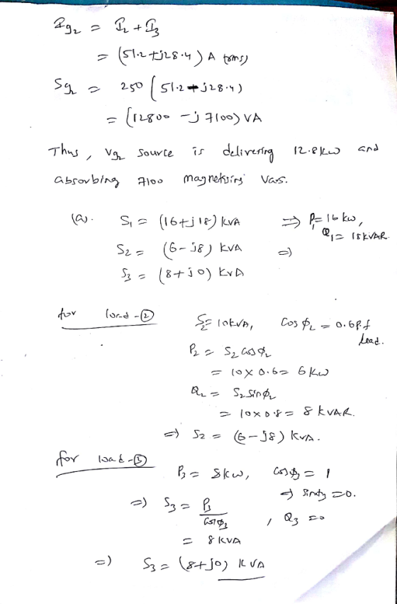
Problem 3. Two three-phase generators supply a three-phase load through separate three-phase lines. The load absorbs...
 Problem 3. Two three-phase generators supply a three-phase load through separate three-phase lines. The load absorbs 30 kW at 0.8 power factor lagging. The line impedance is (1.4 + j1.6) 12 per phase between generator G1 and the load, and (0.8 + jl) 2 per phase between generator G2 and the load. If generator G1 supplies 15 kW at 0.8 power factor lagging, with a terminal voltage of 460 V line-to-line, determine: 1. The voltage at the load terminals. 2....
A balanced 3-0 source serves the following loads: Load 1: 18 kVA at 0.8 PF lagging...
 A balanced 3-0 source serves the following loads: Load 1: 18 kVA at 0.8 PF lagging Load 2: 10 KVA at 0.7 PF leading Load 3: 12 kW at unity PF Load 4: 16 kVA at 0.6 PF lagging The line voltage across the terminals of the load is 208 Vrms and the line impedance is 0.2 +j0.4/0. Find the line voltage and PF at the source. (3 pt) Real part of the line voltage at the source: (3 pt)...
1 A single phase AC system Consider a single phase AC distribution system in which there...
1 A single phase AC system Consider a single phase AC distribution system in which there a single home connected to a 10kVA service transformer. Let’s assume that the primary of the distribution transformer can be modeled as an ideal 240V (rms) AC source and that the effective impedance of the transformer is 2% resistance and 3% reactance. (See lecture notes for converting % to Ohms). Connected to the secondary of the transformer is 200 ft of #6 AWG aluminum...
ll capace, expressed in oks. They 9. The opposition offered to the non offered to the...
 ll capace, expressed in oks. They 9. The opposition offered to the non offered to the flow of a C alensis XE. 1. Inductive Reactance 2. Capacitive Reactance 3. Impedance 4. Resistance 10. The opposition offered to the The opposition offered to the flow of an alteratine curenty inductance, expressed in ons. The symbol for characteristic is XL. 1. Inductive Reactance 2. Capacitive Reactance 3. Impedance when a voltage 11. What is the basic unit of capacitance? Example: A capacitor...
 Consider the two loads in the
circuit in (Figure 1). Load #1 (L1) absorbs S = 56 VA at a lagging
power factor of pf = 0.61. Load #2 (L2) absorbs P2 = 56 W and Q2 =
1 VAR of power. If these loads are powered by a V = 425 V−rms ,
60-Hz source, what impedance needs to be added to the circuit in
order to raise the source's power factor to unity? Express your
answer in rectangular...
Consider the two loads in the
circuit in (Figure 1). Load #1 (L1) absorbs S = 56 VA at a lagging
power factor of pf = 0.61. Load #2 (L2) absorbs P2 = 56 W and Q2 =
1 VAR of power. If these loads are powered by a V = 425 V−rms ,
60-Hz source, what impedance needs to be added to the circuit in
order to raise the source's power factor to unity? Express your
answer in rectangular...
 VO) L1 L2 Line VO LI Power Calculations Learning Goal: In this tutorial, you will practice the calculation of power in circuits containing loads, including the effects of non-ideal transmission lines, and practice how to improve the power factor for an entire system. Many appliances (eg., hair dryers, coffee makers, and refrigerators) and industrial loads are powered by AC sources. The ability to be able to calculate their power needs is important in a number of situations. Before completing this...
 Problem 10.10 3 of 5 Correct Review Constants The load impedance in (Figure 1) absorbs 6 kW and generates 8 kVAR. The sinusoidal voltage source develops 8 kW. Suppose that R-25 Ω Part D For Xemax value of line reactance, find the magnitudes of the total magnetizing vars developed and the total magnetizing vars absorbed Figure Express your answers using three significant figures separated by a comma. 1 of 1 QdeQabs VAR 00040 Submit Previous Answers Request Answer ncorrect: Try...
 Problem 3. Two three-phase generators supply a three-phase load through separate three-phase lines. The load absorbs 30 kW at 0.8 power factor lagging. The line impedance is (1.4 + j1.6) 12 per phase between generator G1 and the load, and (0.8 + jl) 2 per phase between generator G2 and the load. If generator G1 supplies 15 kW at 0.8 power factor lagging, with a terminal voltage of 460 V line-to-line, determine: 1. The voltage at the load terminals. 2....
 A balanced 3-0 source serves the following loads: Load 1: 18 kVA at 0.8 PF lagging Load 2: 10 KVA at 0.7 PF leading Load 3: 12 kW at unity PF Load 4: 16 kVA at 0.6 PF lagging The line voltage across the terminals of the load is 208 Vrms and the line impedance is 0.2 +j0.4/0. Find the line voltage and PF at the source. (3 pt) Real part of the line voltage at the source: (3 pt)...
 ll capace, expressed in oks. They 9. The opposition offered to the non offered to the flow of a C alensis XE. 1. Inductive Reactance 2. Capacitive Reactance 3. Impedance 4. Resistance 10. The opposition offered to the The opposition offered to the flow of an alteratine curenty inductance, expressed in ons. The symbol for characteristic is XL. 1. Inductive Reactance 2. Capacitive Reactance 3. Impedance when a voltage 11. What is the basic unit of capacitance? Example: A capacitor...
Most questions answered within 3 hours.
-
Trace the following recursive methods:
a) isPal with the string “abccda”
b) isAnBn with the string...
asked 58 minutes ago -
1. Which of the following is false about photosynthesis?
A. ATP is the molecule used to...
asked 1 hour ago -
A simple random sample of size n=64 is obtained from a
population with a mean of...
asked 2 hours ago -
(2 dimensions, 1 object, 2 accelerations)
1) A projectile is thrown with a wind. The wind...
asked 3 hours ago -
Brian makes $34,100 per year. How much can Brian expect to
contribute to FICA taxes in...
asked 4 hours ago -
To buy a new house you must borrow $155,000. To do this you take
out a...
asked 4 hours ago -
Spacely Sprockets is evaluating the construction of a new plant
on land the company purchased for...
asked 5 hours ago -
1. Consider a linear regression model of y on K regressors and
an intercept.
(i) Describe...
asked 5 hours ago -
Enter a balanced equation for the reaction between hydrochloric
acid and sodium sulfite.
Express your answer...
asked 5 hours ago -
Give a regular expression describing the language
{x | x ∈ Σ* and x does not...
asked 5 hours ago -
Masses of 1.0 kg, 2.0 kg, and 3.0 kg are each separately subject
to a net...
asked 5 hours ago -
The mode of philosophical argumentation and thought. How do
philosophers think and write? What is important...
asked 5 hours ago