
Homework Answers


Add Answer to:
You need to design for-bit R-2R network digital to analog converter using S k? and io...
Problem 6 (15 points): The general structure of an N -bit R-2R ladder digital to analog...
 Problem 6 (15 points): The general structure of an N -bit R-2R ladder digital to analog converter (DAC) is shown below, where the voltages at each of the input pins are either 0 or 4 V (for binary "O" and "1", respectively). Assume N- 5. A stream of 5-bit unsigned integers, x[n], are applied to the input of this ladder in binary format (for example, if x13-12, which is B01100 in binary, then a2 and a3 are 4V while ao,...
DILU 2d) Analog and Digital Signals i. A 10-bit linear analog-to-digital has reference voltage 3.3 V...
 DILU 2d) Analog and Digital Signals i. A 10-bit linear analog-to-digital has reference voltage 3.3 V such that it operates correct. for input voltage Vin in the range 0 < Vin < 3.3 V. What is its output, in unsigned binary when Vin = 2.267 V? - ii. What is the quantisation error (in volts) for a 10-bit linear analog-to-digital converter with reference voltage 3.3 V?
An 8-bit D/A converter with a 10-volt reference (and Rf = R) has an input of...
An 8-bit D/A converter with a 10-volt reference (and Rf = R) has an input of 10010001. What is the output voltage? What is the step size of the D/A converter? What is the percent resolution?
1900) An analog input module uses an A/D converter with 8-bit resolution. The module range is...
1900) An analog input module uses an A/D converter with 8-bit resolution. The module range is -10 volts to +10 volts. Calculate the module output (digital count) when the input voltage is 3.7 volts. 1) floating point calculation, 2) discrete rounded result (actual digital count), 3) answer-2 minus answer-1 and 4) voltage resolution or smallest detectable change (volts). Assume the minimum digital value is zero. ans:4 thats all that was given to me
plz give correct answer Q5. We are collecting an analog signal ranging from oV to SV...
 plz give correct answer
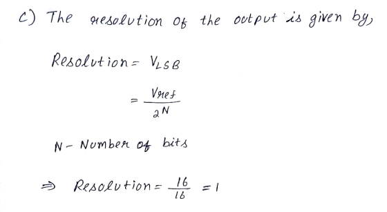
Q5. We are collecting an analog signal ranging from oV to SV with a 3-bit analog-to-digital converter. Calculate the discrete voltage range and fill in the table, and calculate the analog quantization size (resolution). 0.5pt Output states Diserete voltage range IV Analog quantization size (resolution)- 06. Calculate the resolutions for the 2-bit, S-bit, 12-bit, and 16-bit analog-digital converter: Input and output signal ranges from-10V to 10V. 0.5pt 1) 2-bit: 2) 8-bit: 3) 12-bit: 4) 16-bit:
plz give correct answer
Q5. We are collecting an analog signal ranging from oV to SV with a 3-bit analog-to-digital converter. Calculate the discrete voltage range and fill in the table, and calculate the analog quantization size (resolution). 0.5pt Output states Diserete voltage range IV Analog quantization size (resolution)- 06. Calculate the resolutions for the 2-bit, S-bit, 12-bit, and 16-bit analog-digital converter: Input and output signal ranges from-10V to 10V. 0.5pt 1) 2-bit: 2) 8-bit: 3) 12-bit: 4) 16-bit:
Problem 6 Consider a 10-bit dual slop analog-to-digital converter, with reference voltage of -1V, and a clock frequ...
 Problem 6 Consider a 10-bit dual slop analog-to-digital converter, with reference voltage of -1V, and a clock frequency of 1 KHz. The integrating capacitor charges to -8V in the time t, to t2, and discharges at a rate of 10V/sec in the time t2 to t3. What is the input voltage if the binary reading is 1100100000.
Problem 6 Consider a 10-bit dual slop analog-to-digital converter, with reference voltage of -1V, and a clock frequency of 1 KHz. The integrating...
Problem 6 Consider a 10-bit dual slop analog-to-digital converter, with reference voltage of -1V, and a clock frequency of 1 KHz. The integrating capacitor charges to -8V in the time t, to t2, and discharges at a rate of 10V/sec in the time t2 to t3. What is the input voltage if the binary reading is 1100100000.
Problem 6 Consider a 10-bit dual slop analog-to-digital converter, with reference voltage of -1V, and a clock frequency of 1 KHz. The integrating...
EXERCISE 4: (30 MARKS) Given the following circuit in figure 3 of a flash analog-to-digital converter...
 EXERCISE 4: (30 MARKS) Given the following circuit in figure 3 of a flash analog-to-digital converter where VREF = 2.8V. Op-amp comparators Analog input Priority encoder A A 8. Parallel binary output A A A Sampling A pulses Figure 3 - Circuit of exercise 4 a) Determine the resolution of this converter. b) Determine the maximum error quantization error. c) If the sampling period is 10ms, calculate the number of bits per second bitrate) of the ADC. d) Determine the...
What is the output of a 4-bit R-2R DAC if the input digital code is 1101?...
 What is the output of a 4-bit R-2R DAC if the input digital code is 1101? Vref =-8 V. MSBasi 2R Digital input is t101. Y = 1/3 UREF Raik 2R=2K and A) 4V B) 6.33 C) 2.25V D) 4.33V E) 4.5V
Data Converters and Timing Circuits (20 marks) (a) For the timing circuit shown below, use a 1000pF capacitor and find the values of RA and RB that result in an oscillation frequency of 100KHz an...
 Data Converters and Timing Circuits (20 marks) (a) For the timing circuit shown below, use a 1000pF capacitor and find the values of RA and RB that result in an oscillation frequency of 100KHz and a duty cycle of 75% Reset 0.693 R,+2R,)C Discharge Outpat Threshold Trigger Ground Duty-Cle2R R,+2R, ar (b) The 4-Bit Weighted-Resistor DAC Converter shown below is to be expanded into an 8-bit device a. What are the required values of the additional resistors to be added?...
You are asked to design an analog-to-digital converter to digitize an action potential signal. Using your...
You are asked to design an analog-to-digital converter to digitize an action potential signal. Using your knowledge about the frequency and dynamic range of action potential signals and stating all your assumptions, provide your design specifications: a)Sketch the block diagram of the A/D converter. b)Give the type and bandwidth of the anti-aliasing filter. c)Specify the sampling rate of your sampler
 Problem 6 (15 points): The general structure of an N -bit R-2R ladder digital to analog converter (DAC) is shown below, where the voltages at each of the input pins are either 0 or 4 V (for binary "O" and "1", respectively). Assume N- 5. A stream of 5-bit unsigned integers, x[n], are applied to the input of this ladder in binary format (for example, if x13-12, which is B01100 in binary, then a2 and a3 are 4V while ao,...
 DILU 2d) Analog and Digital Signals i. A 10-bit linear analog-to-digital has reference voltage 3.3 V such that it operates correct. for input voltage Vin in the range 0 < Vin < 3.3 V. What is its output, in unsigned binary when Vin = 2.267 V? - ii. What is the quantisation error (in volts) for a 10-bit linear analog-to-digital converter with reference voltage 3.3 V?
 plz give correct answer
Q5. We are collecting an analog signal ranging from oV to SV with a 3-bit analog-to-digital converter. Calculate the discrete voltage range and fill in the table, and calculate the analog quantization size (resolution). 0.5pt Output states Diserete voltage range IV Analog quantization size (resolution)- 06. Calculate the resolutions for the 2-bit, S-bit, 12-bit, and 16-bit analog-digital converter: Input and output signal ranges from-10V to 10V. 0.5pt 1) 2-bit: 2) 8-bit: 3) 12-bit: 4) 16-bit:
plz give correct answer
Q5. We are collecting an analog signal ranging from oV to SV with a 3-bit analog-to-digital converter. Calculate the discrete voltage range and fill in the table, and calculate the analog quantization size (resolution). 0.5pt Output states Diserete voltage range IV Analog quantization size (resolution)- 06. Calculate the resolutions for the 2-bit, S-bit, 12-bit, and 16-bit analog-digital converter: Input and output signal ranges from-10V to 10V. 0.5pt 1) 2-bit: 2) 8-bit: 3) 12-bit: 4) 16-bit:
 Problem 6 Consider a 10-bit dual slop analog-to-digital converter, with reference voltage of -1V, and a clock frequency of 1 KHz. The integrating capacitor charges to -8V in the time t, to t2, and discharges at a rate of 10V/sec in the time t2 to t3. What is the input voltage if the binary reading is 1100100000.
Problem 6 Consider a 10-bit dual slop analog-to-digital converter, with reference voltage of -1V, and a clock frequency of 1 KHz. The integrating...
Problem 6 Consider a 10-bit dual slop analog-to-digital converter, with reference voltage of -1V, and a clock frequency of 1 KHz. The integrating capacitor charges to -8V in the time t, to t2, and discharges at a rate of 10V/sec in the time t2 to t3. What is the input voltage if the binary reading is 1100100000.
Problem 6 Consider a 10-bit dual slop analog-to-digital converter, with reference voltage of -1V, and a clock frequency of 1 KHz. The integrating...
 EXERCISE 4: (30 MARKS) Given the following circuit in figure 3 of a flash analog-to-digital converter where VREF = 2.8V. Op-amp comparators Analog input Priority encoder A A 8. Parallel binary output A A A Sampling A pulses Figure 3 - Circuit of exercise 4 a) Determine the resolution of this converter. b) Determine the maximum error quantization error. c) If the sampling period is 10ms, calculate the number of bits per second bitrate) of the ADC. d) Determine the...
 What is the output of a 4-bit R-2R DAC if the input digital code is 1101? Vref =-8 V. MSBasi 2R Digital input is t101. Y = 1/3 UREF Raik 2R=2K and A) 4V B) 6.33 C) 2.25V D) 4.33V E) 4.5V
 Data Converters and Timing Circuits (20 marks) (a) For the timing circuit shown below, use a 1000pF capacitor and find the values of RA and RB that result in an oscillation frequency of 100KHz and a duty cycle of 75% Reset 0.693 R,+2R,)C Discharge Outpat Threshold Trigger Ground Duty-Cle2R R,+2R, ar (b) The 4-Bit Weighted-Resistor DAC Converter shown below is to be expanded into an 8-bit device a. What are the required values of the additional resistors to be added?...
Most questions answered within 3 hours.
-
We predict that learning statistics will increase a student's
IQ. Those not learning statistics have a...
asked 3 minutes ago -
Write a procedure of how you would separate benzoic acid
(acidic), decane (neutral), and adenine (basic)...
asked 3 minutes ago -
1. What is the pH of 0.773M Sr(OH)2?
2. What is the pH of 0.0133M solution...
asked 12 minutes ago -
At December 31, 2020, Pharoah Company has outstanding three
long-term debt issues. The first is a...
asked 12 minutes ago -
Life requires energy. Use what you know about the energy
transformations that occur in animal cells...
asked 17 minutes ago -
Improving access to medical care has been a challenge in the
U.S. health care system. How...
asked 18 minutes ago -
Engineers must consider the breadths of male heads when
designing helmets. The company researchers have determined...
asked 48 minutes ago -
In the Williamson Ether Synthesis of Phenacetin from
Acetaminophen, sodium methoxide in methanol and 100% ethanol...
asked 53 minutes ago -
If the spin of the earth suddenly changed to spin in the
opposite direction, what effect...
asked 1 hour ago -
An orb weaver spider with a mass of 0.23 grams hangs vertically
by one of its...
asked 1 hour ago -
Determine the sample size required to estimate the mean score on
a standardized test within
2...
asked 1 hour ago -
The idea that one can remain relatively 'anonymous' on the
internet if they so choose, for...
asked 1 hour ago