Packet Tracer Open the Packet Tracer program on your PC. Map a simple network. Include two...
- Packet Tracer
- Open the Packet Tracer program on your PC.
- Map a simple network. Include two PCs, a switch, a router and a
server.
- Wire this network using Copper Straight-Through Cable.
Take a screenshot of the cabled topology and place it
below.
- Assign IP addresses to each PC, the server and the router
interface connected to the switch.
- This can be any IP address, but I suggest a classful private IP
address scheme.
- This can be any IP address, but I suggest a classful private IP
address scheme.
- From PC0, ping the Default Gateway. Take a screenshot
of the successful Replies and place it below.
- From PC1, ping the server. Take a screenshot of the
successful Replies and place it below.
- On the FTP tab of the server, configure a user named
“YourFirstName.” Assign them any password (make sure you remember
it!) and give them all permissions.
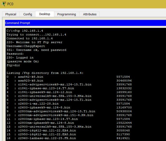
- On either of the PCs, open a Command Prompt and use the ftp
command to access the server.
- Open the Packet Tracer program on your PC.
Login to the FTP server and type the dir command. Take a
screenshot of the directory listing and place it
below.
Homework Answers
Packet Tracer
Step 1:
- Open the Packet Tracer program on your PC.
- Map a simple network. Include two PCs, a switch, a router and a server.
- Wire this network using Copper Straight-Through Cable

Step 2:
- Assign IP addresses to each PC, the server and the router
interface connected to the switch.
- This can be any IP address, but I suggest a classful private IP address scheme.
- From PC0, ping the Default Gateway.

Step 3:
- From PC1, ping the server.

Step 4:
- On the FTP tab of the server, configure a user named “YourFirstName.” Assign them any password (make sure you remember it!) and give them all permissions.
- On either of the PCs, open a Command Prompt and use the ftp command to access the server.
- Login to the FTP server and type the dir command.
Thank you.
Add Answer to:
Packet Tracer
Open the Packet Tracer program on your PC.
Map a simple network. Include two...
can you please help me with this homework. DCOM 101 – Introduction to Data Communications Final Project Instructions: In this Final Project, you will test the skills and knowledge gained throughout th...
can you please help me with this homework. DCOM 101 – Introduction to Data Communications Final Project Instructions: In this Final Project, you will test the skills and knowledge gained throughout this course. The steps listed below are loosely based on the Assignments you have completed thus far, so don’t hesitate to look back and use those resources. Follow the steps in each section, and paste screenshots when prompted. This assignment is worth 10% of your final grade. Basic Network...
PLEASE ATTACH A SCREENSHOT OF YOUR SUCCESSFUL PING IN PACKET TRACER FOR THE END!!!!!!!!!!! THANK YOU! Objectives Part...
 PLEASE ATTACH A SCREENSHOT OF YOUR SUCCESSFUL PING IN
PACKET TRACER FOR THE END!!!!!!!!!!! THANK YOU!
Objectives Part A: Configure a simple static routing . Part B: Configure a simple RIP routing Part A: Configure a simple static routing 1. Create the following network topology on Packet Tracer Router-PT Router-PT Addressing Table Device Interface IP Address Subnet Mask Default Gatewa 10.0.0.1 20.0.0.1 30.0.0.1 20.0.0.2 0.0.0.10 30.0.0.10 N/A 255.0.0.0 255.0.0.0 255.0.0.0 255.0.0.0 255.0.0.0 255.0.0.0 Routero 2/0 NIA NIA NIA 10.0.0.1 30.0.0.1...
PLEASE ATTACH A SCREENSHOT OF YOUR SUCCESSFUL PING IN
PACKET TRACER FOR THE END!!!!!!!!!!! THANK YOU!
Objectives Part A: Configure a simple static routing . Part B: Configure a simple RIP routing Part A: Configure a simple static routing 1. Create the following network topology on Packet Tracer Router-PT Router-PT Addressing Table Device Interface IP Address Subnet Mask Default Gatewa 10.0.0.1 20.0.0.1 30.0.0.1 20.0.0.2 0.0.0.10 30.0.0.10 N/A 255.0.0.0 255.0.0.0 255.0.0.0 255.0.0.0 255.0.0.0 255.0.0.0 Routero 2/0 NIA NIA NIA 10.0.0.1 30.0.0.1...
Configure RIPv2 1. Create the following network topology on Packet Tracer 192.168.2.0/30 192.168.2.2 /30 192.168.2.1/30...
 Configure RIPv2 1. Create the following network topology on Packet Tracer 192.168.2.0/30 192.168.2.2 /30 192.168.2.1/30 192.168.1.1/25 1811 R1 281 192.168.1.129/25 1192.168.1.128 /25 192.168.1.0/25 PC-PT PC1 PC-PT PC2 192.168.1.254/25 192.168.1.126/25 2. Configure the PCs and the routers with network information based on their networks. To configure the routers, use the CLI rather than through the GUI Router1: Fa0/0 192.168.1.1 255.255.255.128 Serial 192.168.2.1 255.255.255.252 with clock rate of 64000 Router2: Fa0/0 192.168.1.129 255.255.255.128 Serial 192.168.2.2 255.255.255.252 Completed 4. Now apply RIPv2 to...
Please use Cisco Packet Tracer to do the following assignment. ut S3M Dmya Bhaskar fotor Assignment...
 Please use Cisco Packet Tracer to do the following
assignment.
ut S3M Dmya Bhaskar fotor Assignment 2: Static Routing & Default routing For the network shown below, assign an appropriate IP address for each host and router interface. Then configure all routers and implement all necessary static/default routes. Try to review routing tables on all routers and test the connectivity of your network using "ping" command before upload pkt file to blackboard. 2950-24 witch メ50t4 Switch 192.163 1.132/30 65 133...
Please use Cisco Packet Tracer to do the following
assignment.
ut S3M Dmya Bhaskar fotor Assignment 2: Static Routing & Default routing For the network shown below, assign an appropriate IP address for each host and router interface. Then configure all routers and implement all necessary static/default routes. Try to review routing tables on all routers and test the connectivity of your network using "ping" command before upload pkt file to blackboard. 2950-24 witch メ50t4 Switch 192.163 1.132/30 65 133...
Using Cisco Packet Tracer, do the following. Your submission should clearly give all CLis in each...
 Using Cisco Packet Tracer, do the following. Your submission should clearly give all CLis in each case and illustrate (a) through (e) through screen captures. (a) Create a network topology with two switches SWO and SW1. SWO should connect four devices i.e., two computers PCO and PC1 and two printers P1 and P2. SW1, on the other hand, connects computers PC2 through PCS and a DHCP server SO. (b) Configure the connection in (a) so that all devices get their...
PLEASE ATTACH A SCREENSHOT OF THE RE-POPULTATED TABLE AT THE END Objectives Part A: Configure Devices and Verify Conne...
 PLEASE ATTACH A SCREENSHOT OF THE RE-POPULTATED TABLE AT
THE END
Objectives Part A: Configure Devices and Verify Connectivity . Part B: Gather Information with Show Commands Tasks Create the following network topology on Packet Tracer Addressing Table 10.10.10.0/24 10 SW1 Device InterfaceIP Address Subnet Mask Default Gateway .1 PC1 10.10.10.1 255.255.255.0 NIA f0/o RTA 10.10.20.1 255.255.255.0NIA f0/1 RTA .1 PC1 255.255.255.010.10.10.1 NIC 10.10.10.10 10.10.20.0/24 PC2 NIC 10.10.20.10 255.255.255.0 10.10.20.1 10 SW2 PC2 Part A: Configure Devices and Verify Connectivity...
PLEASE ATTACH A SCREENSHOT OF THE RE-POPULTATED TABLE AT
THE END
Objectives Part A: Configure Devices and Verify Connectivity . Part B: Gather Information with Show Commands Tasks Create the following network topology on Packet Tracer Addressing Table 10.10.10.0/24 10 SW1 Device InterfaceIP Address Subnet Mask Default Gateway .1 PC1 10.10.10.1 255.255.255.0 NIA f0/o RTA 10.10.20.1 255.255.255.0NIA f0/1 RTA .1 PC1 255.255.255.010.10.10.1 NIC 10.10.10.10 10.10.20.0/24 PC2 NIC 10.10.20.10 255.255.255.0 10.10.20.1 10 SW2 PC2 Part A: Configure Devices and Verify Connectivity...
HINTS FOR THE MACHINE PROELEM 1 Problem 1.1 a) i. DHCP. CHCP D4CFOffer Desanbe in detatl...
 HINTS FOR THE MACHINE PROELEM 1 Problem 1.1 a) i. DHCP. CHCP D4CFOffer Desanbe in detatl the 1-step process that the DHCP Client requests for the P Address frcm the DHCF Serrer. Capture te pockage DHC PDiscovez DHCP0fter, DHCPRequest, DHC PAck to shotw their struuctuTes. i ARP. Describe in dtail the 5-step process of a machine or router perocning ARP protocol to ind the phrsical address of the network node with the known IF address Captue the packages: ARP Request,...
1. Let’s consider the network shown in Figure 1 where Snort is deployed. 1.1: In Figure...
 1. Let’s consider the network shown in Figure 1 where Snort is
deployed.
1.1: In Figure 1, why is Snort deployed in the DMZ instead of
the Internal Network? (9 points)
1.2: In Figure 1, say True or False to the following statement:
“Snort can see both incoming packets from the left firewall and
outgoing packets from the right firewall”. (5 points)
1.3: In Figure 1, assume a packet P matches the following Snort
rule when the packet is analyzed...
1. Let’s consider the network shown in Figure 1 where Snort is
deployed.
1.1: In Figure 1, why is Snort deployed in the DMZ instead of
the Internal Network? (9 points)
1.2: In Figure 1, say True or False to the following statement:
“Snort can see both incoming packets from the left firewall and
outgoing packets from the right firewall”. (5 points)
1.3: In Figure 1, assume a packet P matches the following Snort
rule when the packet is analyzed...
Hi please help me solve this! Been stuck on this for a long time. I don;t...
 Hi please help me solve this! Been stuck on this for a long
time. I don;t know how to upload the file but packet tracer is
required. Please help!! I don;t know how to begin or finish
this!
Regards
200.1.1.2 /24 200.1.1.1/24 Subnet 4 1941 PC-PT PCO 1941 Router0 Router1 Network Address 192.168.21.0/24 5 subnets required Serial link 4 VLANS required VLAN 20 (Staf) (Subnet 0) VLAN 30 (Student) (Subnet 1) VLAN 40 (Server) (Subnet 2) VLAN 100 (Management)(Subnet 3)...
Hi please help me solve this! Been stuck on this for a long
time. I don;t know how to upload the file but packet tracer is
required. Please help!! I don;t know how to begin or finish
this!
Regards
200.1.1.2 /24 200.1.1.1/24 Subnet 4 1941 PC-PT PCO 1941 Router0 Router1 Network Address 192.168.21.0/24 5 subnets required Serial link 4 VLANS required VLAN 20 (Staf) (Subnet 0) VLAN 30 (Student) (Subnet 1) VLAN 40 (Server) (Subnet 2) VLAN 100 (Management)(Subnet 3)...
Description: In this assignment, you will be launching a denial of service attack on a web...
Description: In this assignment, you will be launching a denial of service attack on a web server. We will be using hping3, a command-line oriented network security tool inside Kali Linux (an advanced penetration testing Linux distribution). Setting up the victim machine Download the Windows XP virtual machine with WebGoat server installed, using the following link. We will use this machine as the victim machine and launch a DoS attack on the WebGoat server.https://drive.google.com/open?id=0BwCbaZv8DevUejBPWlNHREFVc2s Open the victim machine and launch...
 PLEASE ATTACH A SCREENSHOT OF YOUR SUCCESSFUL PING IN
PACKET TRACER FOR THE END!!!!!!!!!!! THANK YOU!
Objectives Part A: Configure a simple static routing . Part B: Configure a simple RIP routing Part A: Configure a simple static routing 1. Create the following network topology on Packet Tracer Router-PT Router-PT Addressing Table Device Interface IP Address Subnet Mask Default Gatewa 10.0.0.1 20.0.0.1 30.0.0.1 20.0.0.2 0.0.0.10 30.0.0.10 N/A 255.0.0.0 255.0.0.0 255.0.0.0 255.0.0.0 255.0.0.0 255.0.0.0 Routero 2/0 NIA NIA NIA 10.0.0.1 30.0.0.1...
PLEASE ATTACH A SCREENSHOT OF YOUR SUCCESSFUL PING IN
PACKET TRACER FOR THE END!!!!!!!!!!! THANK YOU!
Objectives Part A: Configure a simple static routing . Part B: Configure a simple RIP routing Part A: Configure a simple static routing 1. Create the following network topology on Packet Tracer Router-PT Router-PT Addressing Table Device Interface IP Address Subnet Mask Default Gatewa 10.0.0.1 20.0.0.1 30.0.0.1 20.0.0.2 0.0.0.10 30.0.0.10 N/A 255.0.0.0 255.0.0.0 255.0.0.0 255.0.0.0 255.0.0.0 255.0.0.0 Routero 2/0 NIA NIA NIA 10.0.0.1 30.0.0.1...
 Configure RIPv2 1. Create the following network topology on Packet Tracer 192.168.2.0/30 192.168.2.2 /30 192.168.2.1/30 192.168.1.1/25 1811 R1 281 192.168.1.129/25 1192.168.1.128 /25 192.168.1.0/25 PC-PT PC1 PC-PT PC2 192.168.1.254/25 192.168.1.126/25 2. Configure the PCs and the routers with network information based on their networks. To configure the routers, use the CLI rather than through the GUI Router1: Fa0/0 192.168.1.1 255.255.255.128 Serial 192.168.2.1 255.255.255.252 with clock rate of 64000 Router2: Fa0/0 192.168.1.129 255.255.255.128 Serial 192.168.2.2 255.255.255.252 Completed 4. Now apply RIPv2 to...
 Please use Cisco Packet Tracer to do the following
assignment.
ut S3M Dmya Bhaskar fotor Assignment 2: Static Routing & Default routing For the network shown below, assign an appropriate IP address for each host and router interface. Then configure all routers and implement all necessary static/default routes. Try to review routing tables on all routers and test the connectivity of your network using "ping" command before upload pkt file to blackboard. 2950-24 witch メ50t4 Switch 192.163 1.132/30 65 133...
Please use Cisco Packet Tracer to do the following
assignment.
ut S3M Dmya Bhaskar fotor Assignment 2: Static Routing & Default routing For the network shown below, assign an appropriate IP address for each host and router interface. Then configure all routers and implement all necessary static/default routes. Try to review routing tables on all routers and test the connectivity of your network using "ping" command before upload pkt file to blackboard. 2950-24 witch メ50t4 Switch 192.163 1.132/30 65 133...
 Using Cisco Packet Tracer, do the following. Your submission should clearly give all CLis in each case and illustrate (a) through (e) through screen captures. (a) Create a network topology with two switches SWO and SW1. SWO should connect four devices i.e., two computers PCO and PC1 and two printers P1 and P2. SW1, on the other hand, connects computers PC2 through PCS and a DHCP server SO. (b) Configure the connection in (a) so that all devices get their...
 PLEASE ATTACH A SCREENSHOT OF THE RE-POPULTATED TABLE AT
THE END
Objectives Part A: Configure Devices and Verify Connectivity . Part B: Gather Information with Show Commands Tasks Create the following network topology on Packet Tracer Addressing Table 10.10.10.0/24 10 SW1 Device InterfaceIP Address Subnet Mask Default Gateway .1 PC1 10.10.10.1 255.255.255.0 NIA f0/o RTA 10.10.20.1 255.255.255.0NIA f0/1 RTA .1 PC1 255.255.255.010.10.10.1 NIC 10.10.10.10 10.10.20.0/24 PC2 NIC 10.10.20.10 255.255.255.0 10.10.20.1 10 SW2 PC2 Part A: Configure Devices and Verify Connectivity...
PLEASE ATTACH A SCREENSHOT OF THE RE-POPULTATED TABLE AT
THE END
Objectives Part A: Configure Devices and Verify Connectivity . Part B: Gather Information with Show Commands Tasks Create the following network topology on Packet Tracer Addressing Table 10.10.10.0/24 10 SW1 Device InterfaceIP Address Subnet Mask Default Gateway .1 PC1 10.10.10.1 255.255.255.0 NIA f0/o RTA 10.10.20.1 255.255.255.0NIA f0/1 RTA .1 PC1 255.255.255.010.10.10.1 NIC 10.10.10.10 10.10.20.0/24 PC2 NIC 10.10.20.10 255.255.255.0 10.10.20.1 10 SW2 PC2 Part A: Configure Devices and Verify Connectivity...
 HINTS FOR THE MACHINE PROELEM 1 Problem 1.1 a) i. DHCP. CHCP D4CFOffer Desanbe in detatl the 1-step process that the DHCP Client requests for the P Address frcm the DHCF Serrer. Capture te pockage DHC PDiscovez DHCP0fter, DHCPRequest, DHC PAck to shotw their struuctuTes. i ARP. Describe in dtail the 5-step process of a machine or router perocning ARP protocol to ind the phrsical address of the network node with the known IF address Captue the packages: ARP Request,...
 1. Let’s consider the network shown in Figure 1 where Snort is
deployed.
1.1: In Figure 1, why is Snort deployed in the DMZ instead of
the Internal Network? (9 points)
1.2: In Figure 1, say True or False to the following statement:
“Snort can see both incoming packets from the left firewall and
outgoing packets from the right firewall”. (5 points)
1.3: In Figure 1, assume a packet P matches the following Snort
rule when the packet is analyzed...
1. Let’s consider the network shown in Figure 1 where Snort is
deployed.
1.1: In Figure 1, why is Snort deployed in the DMZ instead of
the Internal Network? (9 points)
1.2: In Figure 1, say True or False to the following statement:
“Snort can see both incoming packets from the left firewall and
outgoing packets from the right firewall”. (5 points)
1.3: In Figure 1, assume a packet P matches the following Snort
rule when the packet is analyzed...
 Hi please help me solve this! Been stuck on this for a long
time. I don;t know how to upload the file but packet tracer is
required. Please help!! I don;t know how to begin or finish
this!
Regards
200.1.1.2 /24 200.1.1.1/24 Subnet 4 1941 PC-PT PCO 1941 Router0 Router1 Network Address 192.168.21.0/24 5 subnets required Serial link 4 VLANS required VLAN 20 (Staf) (Subnet 0) VLAN 30 (Student) (Subnet 1) VLAN 40 (Server) (Subnet 2) VLAN 100 (Management)(Subnet 3)...
Hi please help me solve this! Been stuck on this for a long
time. I don;t know how to upload the file but packet tracer is
required. Please help!! I don;t know how to begin or finish
this!
Regards
200.1.1.2 /24 200.1.1.1/24 Subnet 4 1941 PC-PT PCO 1941 Router0 Router1 Network Address 192.168.21.0/24 5 subnets required Serial link 4 VLANS required VLAN 20 (Staf) (Subnet 0) VLAN 30 (Student) (Subnet 1) VLAN 40 (Server) (Subnet 2) VLAN 100 (Management)(Subnet 3)...
Most questions answered within 3 hours.
-
Which characteristics are shared by surfactants and fatty
amphiphiles (such as cetyl alcohol)?
I Surface active...
asked 35 seconds ago -
A 7,000-seat theater is interested in determining whether there
is a difference in attendance between shows...
asked 5 minutes ago -
the
acceleration of a block m=1.00kg attached to a spring is given by
a=-0.302 m/s^2) cos{2.41rad/s}t....
asked 4 minutes ago -
Kevin Hall borrowed some money from his friend and promised to
repay him $1,260, $1,370, $1,530,...
asked 5 minutes ago -
1) What is the element with the electron: [Ne] 3s^2
3p^5?
2) The number of unpaired...
asked 6 minutes ago -
A blacksmith cools a 1.22-kg chunk of iron, initially at a
temperature of 650.0∘C, by trickling...
asked 29 minutes ago -
Air at 222 °F flows at standard atmospheric pressure in a pipe
at a rate of...
asked 30 minutes ago -
what factors can influence the results of the memory
stand experiment?
asked 30 minutes ago -
For eggplants, there are three colors (phenotypes) :
dark purple, light purple and white. A white...
asked 33 minutes ago -
software testing
without making any changes to the java classes provided below,
come up with some...
asked 48 minutes ago -
The demand for a product is normally distributed with an average
daily demand of 90 units...
asked 1 hour ago -
Modos Company has deposited $3,500 in checks received from
customers. It has written $1,400 in checks...
asked 1 hour ago