
Homework Answers
Add Answer to:
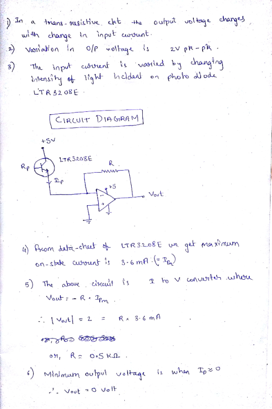
Design a trans-resistive circuit to detect IR radiation using the LTR3208E, an LM324, and passive...
Draw a circuit to output the following wave as 1V pk-pk sine wave centered at 0V and output to be...
 Draw a circuit to output the following wave as 1V
pk-pk sine wave centered at 0V and output to be out of phase
180degrees with respect to input.
Problem #5 [10 points]: Design a circuit with the following criteria. Assume existence of +5V power supply. Draw your circuit and show your work. i. Input signal that operates between Vin -5V- +5V, and capable of sourcing or sinking 500 x 10^-6 A. ii. Output signal nominally outputs between Vout 0V 5V,...
Draw a circuit to output the following wave as 1V
pk-pk sine wave centered at 0V and output to be out of phase
180degrees with respect to input.
Problem #5 [10 points]: Design a circuit with the following criteria. Assume existence of +5V power supply. Draw your circuit and show your work. i. Input signal that operates between Vin -5V- +5V, and capable of sourcing or sinking 500 x 10^-6 A. ii. Output signal nominally outputs between Vout 0V 5V,...
Problem #5 [10 points]: Design a circuit with the following criteria. Assume existence of +5V pow...
 Problem #5 [10 points]: Design a circuit with the following criteria. Assume existence of +5V power supply. Draw your circuit and show your work. i. Input signal that operates between Vin -5V- +5V, and capable of sourcing or sinking 500 x 10^-6 A. ii. Output signal nominally outputs between Vout 0V 5V, and capable of sinking 1 mA from an external device with an output no more than 0.1 V
Problem #5 [10 points]: Design a circuit with the following...
Problem #5 [10 points]: Design a circuit with the following criteria. Assume existence of +5V power supply. Draw your circuit and show your work. i. Input signal that operates between Vin -5V- +5V, and capable of sourcing or sinking 500 x 10^-6 A. ii. Output signal nominally outputs between Vout 0V 5V, and capable of sinking 1 mA from an external device with an output no more than 0.1 V
Problem #5 [10 points]: Design a circuit with the following...
2. Consider the resistive circuit below. 6V 133 + 15V R3 lc R1 80 V 4A...
 2. Consider the resistive circuit below. 6V 133 + 15V R3 lc R1 80 V 4A R4 5V D 100 a. Find Vx, Vy, lA, IB, lc, ID, and le. b. Find the power for each of the sources, using the passive sign convention Do any of the sources dissipate power?
4. (25 points) (Show all work) Design an inverter circuit using a NMOS transistor and a...
 4. (25 points) (Show all work) Design an inverter circuit using a NMOS transistor and a resistor with Vout-5.0 when Vin-OV and Vout-0.3 V when Vin-SV with Kn-300uA/V" and a VrN = 1 V. Use ID-Kn(VGS-VTNJVDs. You have a 5V supply available to power the circuit.
Question 3 a) Design the resistive load based NMOS inverter in Figure Q3a to provide VOL...
 Question 3 a) Design the resistive load based NMOS inverter in Figure Q3a to provide VOL = 200 mV and to draw a supply current of 80 pA in the low-output state. Let the transistor be specified to have VTN = 0.7 V, KN = 125 JA/V, and I = 0. The power supply VoD = 2.5 V. State any assumptions made. Calculate the required values of W/L and Rp. ii) How much power is drawn from Voo when the...
(a) Design the circuit (Find values for Rc, Rei and Rez) to amplify a 12mV sinusoidal...
 (a) Design the circuit (Find values for Rc, Rei and Rez) to amplify a 12mV sinusoidal signal from a microphone to a 0.4 V sinusoidal output signal, and make le = 0.2 mA. (20 points) (6) Draw complete small signal equivalent circuit of the amplifier. Clearly label all components. (Spoints) (c) Find values of input resistance (Rin), output resistance (Rout), and open circuit voltage gain ( Avo). (20 points) Assume B = 100, VBE.ON=0.7V, VA=00, and capacitors are very large...
Design a circuit and Arduino program that accomplishes the following: An IR distance sensor will detect the presence (t...
Design a circuit and Arduino program that accomplishes the following: An IR distance sensor will detect the presence (through waving of a hand) A H-Bridge circuit with 9V battery power will control the direction of the DC motor as described in Chapter 4 (pp. 70-79) of your textbook. When a hand is waved over the IR sensor, the motor moves in one direction (simulating opening a door). There is a 2 second pause, and then the motor moves in the...
Problemuǐ(30 points) Consider the circuit in Figure 1 1Ω 4A Figure I. DC resistive circuit Submit...
 Problemuǐ(30 points) Consider the circuit in Figure 1 1Ω 4A Figure I. DC resistive circuit Submit these Numerical Values in the Answer Sheet 5 points:IA 5 points: IA 5 points:VV 5 points: V.V 5 points : Power of the 2 Ω resistor Li 5 points: Power of the current source [W 1.a : Use KCL, KVL, and Ohm's Law to calculate 1 [AJ. I2 IA]. V1 IV] and V2 [V] 工 20-120 A 112 2. L.b: Verify your results by...
Build an Op-Amp Circuit Network. Note you only have a power source of 5V available. You...
Build an Op-Amp Circuit Network. Note you only have a power source of 5V available. You have a voltage signal that latches at a constant 1.5V. Create a difference circuit to produce an output voltage of 2V. Put P/Ns and element values in your design. Show your work. From part a)’s output voltage, assign that now as a reference voltage (Vref) to compare to an analog sensor signal (Vin) that can range between 0V – 5V. Make sure your circuit...
Learning Goal: To analyze and design a passive, first-order low-pass filter using a series RL circuit....
 Learning Goal: To analyze and design a passive, first-order low-pass filter using a series RL circuit. The analysis and design will be repeated for a series RC circuit. An electrocardiogram needs to detect periodic signals of approximately 1 Hz (since the resting heart rate of a healthy adult is between 55 and 70 beats per minute). The instrument operates in an electrical environment that is very noisy with a frequency of 60 Hz. It is desirable to have a low-pass...
 Draw a circuit to output the following wave as 1V
pk-pk sine wave centered at 0V and output to be out of phase
180degrees with respect to input.
Problem #5 [10 points]: Design a circuit with the following criteria. Assume existence of +5V power supply. Draw your circuit and show your work. i. Input signal that operates between Vin -5V- +5V, and capable of sourcing or sinking 500 x 10^-6 A. ii. Output signal nominally outputs between Vout 0V 5V,...
Draw a circuit to output the following wave as 1V
pk-pk sine wave centered at 0V and output to be out of phase
180degrees with respect to input.
Problem #5 [10 points]: Design a circuit with the following criteria. Assume existence of +5V power supply. Draw your circuit and show your work. i. Input signal that operates between Vin -5V- +5V, and capable of sourcing or sinking 500 x 10^-6 A. ii. Output signal nominally outputs between Vout 0V 5V,...
 Problem #5 [10 points]: Design a circuit with the following criteria. Assume existence of +5V power supply. Draw your circuit and show your work. i. Input signal that operates between Vin -5V- +5V, and capable of sourcing or sinking 500 x 10^-6 A. ii. Output signal nominally outputs between Vout 0V 5V, and capable of sinking 1 mA from an external device with an output no more than 0.1 V
Problem #5 [10 points]: Design a circuit with the following...
Problem #5 [10 points]: Design a circuit with the following criteria. Assume existence of +5V power supply. Draw your circuit and show your work. i. Input signal that operates between Vin -5V- +5V, and capable of sourcing or sinking 500 x 10^-6 A. ii. Output signal nominally outputs between Vout 0V 5V, and capable of sinking 1 mA from an external device with an output no more than 0.1 V
Problem #5 [10 points]: Design a circuit with the following...
 2. Consider the resistive circuit below. 6V 133 + 15V R3 lc R1 80 V 4A R4 5V D 100 a. Find Vx, Vy, lA, IB, lc, ID, and le. b. Find the power for each of the sources, using the passive sign convention Do any of the sources dissipate power?
 4. (25 points) (Show all work) Design an inverter circuit using a NMOS transistor and a resistor with Vout-5.0 when Vin-OV and Vout-0.3 V when Vin-SV with Kn-300uA/V" and a VrN = 1 V. Use ID-Kn(VGS-VTNJVDs. You have a 5V supply available to power the circuit.
 Question 3 a) Design the resistive load based NMOS inverter in Figure Q3a to provide VOL = 200 mV and to draw a supply current of 80 pA in the low-output state. Let the transistor be specified to have VTN = 0.7 V, KN = 125 JA/V, and I = 0. The power supply VoD = 2.5 V. State any assumptions made. Calculate the required values of W/L and Rp. ii) How much power is drawn from Voo when the...
 (a) Design the circuit (Find values for Rc, Rei and Rez) to amplify a 12mV sinusoidal signal from a microphone to a 0.4 V sinusoidal output signal, and make le = 0.2 mA. (20 points) (6) Draw complete small signal equivalent circuit of the amplifier. Clearly label all components. (Spoints) (c) Find values of input resistance (Rin), output resistance (Rout), and open circuit voltage gain ( Avo). (20 points) Assume B = 100, VBE.ON=0.7V, VA=00, and capacitors are very large...
 Problemuǐ(30 points) Consider the circuit in Figure 1 1Ω 4A Figure I. DC resistive circuit Submit these Numerical Values in the Answer Sheet 5 points:IA 5 points: IA 5 points:VV 5 points: V.V 5 points : Power of the 2 Ω resistor Li 5 points: Power of the current source [W 1.a : Use KCL, KVL, and Ohm's Law to calculate 1 [AJ. I2 IA]. V1 IV] and V2 [V] 工 20-120 A 112 2. L.b: Verify your results by...
 Learning Goal: To analyze and design a passive, first-order low-pass filter using a series RL circuit. The analysis and design will be repeated for a series RC circuit. An electrocardiogram needs to detect periodic signals of approximately 1 Hz (since the resting heart rate of a healthy adult is between 55 and 70 beats per minute). The instrument operates in an electrical environment that is very noisy with a frequency of 60 Hz. It is desirable to have a low-pass...
Most questions answered within 3 hours.
-
A 10.000 g sample of water contains 11.19% H by mass. what
should be the %H...
asked 3 minutes ago -
Consider an investment game among 2 players. Each player can
either invest,
i, or not invest,-i....
asked 1 minute ago -
The time taken to complete a particular task is normally
distributed with a standard deviation of...
asked 11 minutes ago -
we have heteroskedasticity in a regression when:
When the variance of error terms changes when an...
asked 20 minutes ago -
Explain some different types of fungi. State the different
divisions undergo by fungi.
asked 33 minutes ago -
The shortest time that 120 C can flow through a 20 A circuit
breaker without tripping...
asked 34 minutes ago -
A software design pattern is a general, reusable solution to a
commonly occurring problem, acting as...
asked 36 minutes ago -
The mean waiting time at the drive-through of a fast-food
restaurant from the time an order...
asked 53 minutes ago -
The pitch (p) of a helix is defined as p = dn, in which n is...
asked 55 minutes ago -
Do you agree that the declining stock of social capital is the
blame for the failure...
asked 59 minutes ago -
A researcher is interested in whether coffee consumption helps
with performance on reading comprehension tasks. The...
asked 1 hour ago -
it has been estimated since the beginning of the human race that
about 133 metric ton...
asked 1 hour ago