Is there anyone out there could help me, please.. Objective: - Write a ladder logic program to s...
Is there anyone out there could help me, please..
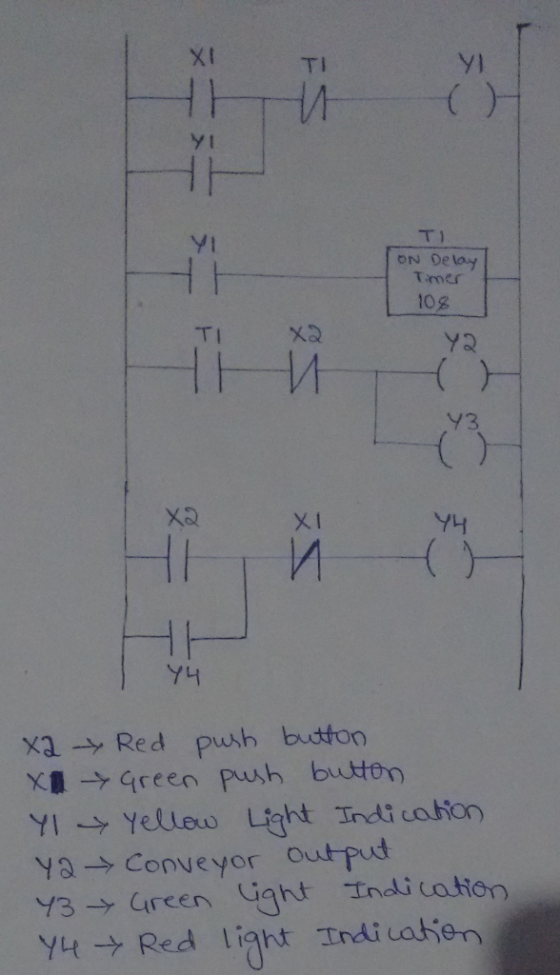
Objective:
- Write a ladder logic program to simulate an industrial process.
- Explore additional PLC/HMI data types.
Program Requirements:
Part 1:
~~Red Button will be used to stop the system, Red light only should be on.
~~Green button press:
-Yellow Light will flash for 10 seconds.
-After elapsed time yellow light goes off, illuminate green light then the conveyor should start.
Make sure the buttons remain in proper state. (Not momentary)
Phase 2:
Include a status window to display system states: Running, stopped, and Caution about to start to coincide with yellow light flash.
Note: Status Window does not utilize a binary or boolean data type.
Homework Answers
Add Answer to:
Is there anyone out there could help me, please.. Objective: - Write a ladder logic program to s...
Hi, anyone can help me? thank you so much Step 7K: Create a Program Create a...
 Hi, anyone can help me? thank you so much
Step 7K: Create a Program Create a small program to turn on and off the conveyor utilizing buttons/tags on the HMI, not the hardwired switch Remember you SHOULD NEVER energize an "Input" data file bit, or use it as an internal relay. You will be utilizing your "binary" data file to create internal relays Use two buttons, 1 for start, 1 for stop Latching of the operation is required, but not...
Hi, anyone can help me? thank you so much
Step 7K: Create a Program Create a small program to turn on and off the conveyor utilizing buttons/tags on the HMI, not the hardwired switch Remember you SHOULD NEVER energize an "Input" data file bit, or use it as an internal relay. You will be utilizing your "binary" data file to create internal relays Use two buttons, 1 for start, 1 for stop Latching of the operation is required, but not...
please solve all the questions Q1 (30 pts) Design a state-based PLC program to control a...
 please solve all the questions
Q1 (30 pts) Design a state-based PLC program to control a motor. The system specification is as follows. • Press a normally open push button, the motor will start. Motor stop will stop after 5 minutes or a normally close push button is pressed. . When the motor is running, a read light is ON. When the motor is stopped, a green light is ON. Use the "Fail Safe" concept, i.e., if the wire of...
please solve all the questions
Q1 (30 pts) Design a state-based PLC program to control a motor. The system specification is as follows. • Press a normally open push button, the motor will start. Motor stop will stop after 5 minutes or a normally close push button is pressed. . When the motor is running, a read light is ON. When the motor is stopped, a green light is ON. Use the "Fail Safe" concept, i.e., if the wire of...
Lab 3 word p develop a ladder diagram from a EGN 4023 the objective of this...
 Lab 3 word p develop a ladder diagram from a EGN 4023 the objective of this practical exercise is to introduce to using interlocking and safety operation techniques. Equipment " Computer with installed software to control and program the PLC Process Application: Water Tank Level The process turning a discharge pump on or off. The modes of operation are to be programmed as follows: by shown in the Figure below is to be used to control the level of water...
THIS IS A PLC PROGRAM CALLED SIMATIC MANGER. WE NEED TO WRITE LADDER LOGIC PROGRAM AND FORM A SYM...
 THIS IS A PLC PROGRAM CALLED
SIMATIC MANGER. WE NEED TO WRITE LADDER LOGIC PROGRAM AND FORM A
SYMBOL TABLE
We were unable to transcribe this imageThe painting turn-table system shown in the following figure has a DC motor, two limit switches, a pneumatic cylinder, a start button and two spray guns. The paint guns are activated by 24 V DC voltage. The motor turns the table only in one direction Red Spray gun Blue spray gun Limit switch trigger...
THIS IS A PLC PROGRAM CALLED
SIMATIC MANGER. WE NEED TO WRITE LADDER LOGIC PROGRAM AND FORM A
SYMBOL TABLE
We were unable to transcribe this imageThe painting turn-table system shown in the following figure has a DC motor, two limit switches, a pneumatic cylinder, a start button and two spray guns. The paint guns are activated by 24 V DC voltage. The motor turns the table only in one direction Red Spray gun Blue spray gun Limit switch trigger...
 Hi, anyone can help me? thank you so much
Step 7K: Create a Program Create a small program to turn on and off the conveyor utilizing buttons/tags on the HMI, not the hardwired switch Remember you SHOULD NEVER energize an "Input" data file bit, or use it as an internal relay. You will be utilizing your "binary" data file to create internal relays Use two buttons, 1 for start, 1 for stop Latching of the operation is required, but not...
Hi, anyone can help me? thank you so much
Step 7K: Create a Program Create a small program to turn on and off the conveyor utilizing buttons/tags on the HMI, not the hardwired switch Remember you SHOULD NEVER energize an "Input" data file bit, or use it as an internal relay. You will be utilizing your "binary" data file to create internal relays Use two buttons, 1 for start, 1 for stop Latching of the operation is required, but not...
 please solve all the questions
Q1 (30 pts) Design a state-based PLC program to control a motor. The system specification is as follows. • Press a normally open push button, the motor will start. Motor stop will stop after 5 minutes or a normally close push button is pressed. . When the motor is running, a read light is ON. When the motor is stopped, a green light is ON. Use the "Fail Safe" concept, i.e., if the wire of...
please solve all the questions
Q1 (30 pts) Design a state-based PLC program to control a motor. The system specification is as follows. • Press a normally open push button, the motor will start. Motor stop will stop after 5 minutes or a normally close push button is pressed. . When the motor is running, a read light is ON. When the motor is stopped, a green light is ON. Use the "Fail Safe" concept, i.e., if the wire of...
 Lab 3 word p develop a ladder diagram from a EGN 4023 the objective of this practical exercise is to introduce to using interlocking and safety operation techniques. Equipment " Computer with installed software to control and program the PLC Process Application: Water Tank Level The process turning a discharge pump on or off. The modes of operation are to be programmed as follows: by shown in the Figure below is to be used to control the level of water...
 THIS IS A PLC PROGRAM CALLED
SIMATIC MANGER. WE NEED TO WRITE LADDER LOGIC PROGRAM AND FORM A
SYMBOL TABLE
We were unable to transcribe this imageThe painting turn-table system shown in the following figure has a DC motor, two limit switches, a pneumatic cylinder, a start button and two spray guns. The paint guns are activated by 24 V DC voltage. The motor turns the table only in one direction Red Spray gun Blue spray gun Limit switch trigger...
THIS IS A PLC PROGRAM CALLED
SIMATIC MANGER. WE NEED TO WRITE LADDER LOGIC PROGRAM AND FORM A
SYMBOL TABLE
We were unable to transcribe this imageThe painting turn-table system shown in the following figure has a DC motor, two limit switches, a pneumatic cylinder, a start button and two spray guns. The paint guns are activated by 24 V DC voltage. The motor turns the table only in one direction Red Spray gun Blue spray gun Limit switch trigger...
Most questions answered within 3 hours.
-
1.why should every employee should know his rights in the
workplace?
2.why the industrial officer union...
asked 1 minute ago -
Consider a binomial experiment with n = 9 trials where the
probability of success on a...
asked 1 minute ago -
6. Given the following equations:
(i) 3 A2+ + 2 D → 3 A + 2...
asked 5 minutes ago -
Find the percentage of the total work lost to friction if 20.8 J
of work is...
asked 4 minutes ago -
Consider the oscillator position x=2 cos(2π t), where time t is
measured in seconds. What is...
asked 5 minutes ago -
A firm has beginning inventory of 340 units at a cost of $9
each. Production during...
asked 20 minutes ago -
Find the standard deviation of the following 6 price values of
the S & P 500...
asked 26 minutes ago -
Suppose Chris is offered the following gamble: with probability
0.1 he will win $90, with probability...
asked 28 minutes ago -
Adil knows that he has one of 3 possible liquid unknowns:
tetrahyrofuran (bp 65-67°C), ethyl acetate...
asked 39 minutes ago -
Fill in with the correct letters:
When considering a Supply and demand curve, what happens in...
asked 39 minutes ago -
Fiscal stimulus is weaker in an open economy because the
greater aggregate demand resulting from the...
asked 43 minutes ago -
Identify the components of replication, transcription, and
translation processes.
Replication
transcription
translation
DNA polymerase, deoxynucleoside triphosphate,...
asked 47 minutes ago