
Please show all the clearly step
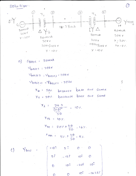
Y11 ist j30 and Y44 isnt -j12.85
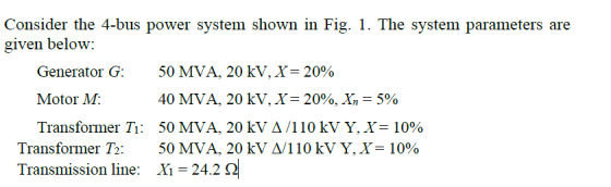
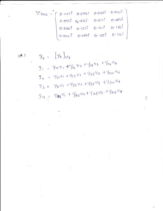
3 4 T2 nu)M Fig. 1 A 4-bus power system Choose 50MVA of the generator as the power base Sbas. Then convert all the impedance parameters into per unit values. a) b) Draw the network circuit diagram and indicate clearly the per unit values of circuit elements. Neglect the phase shift of the Y/A transformers and Xn i.e. Xp-0 in the circuit diagram. MATLAB, to compute the impedance matrix if needed. the network equations for the system using the result of c) c) Find bus admittance matrix Yus and impedance matrix Zbus. Use software, eg d) Denote V, and k the voltage and current at bus k, k = 1, 2, 3, 4, Write down
Homework Answers
Add Answer to:
Consider the 4-bus power system shown in Fig. 1. The system parameters are given below: 50 MVA, 2...
Four-bus power system shown in Fig. 1 are as follows: Generator G1: 200 MVA, 7.2 kv,...
 Four-bus power system shown in Fig. 1 are as follows: Generator G1: 200 MVA, 7.2 kv, X -0.15 p.u Generator G2: 250 MVA, 9.6 kV, X-0.12 p.u Generator G3: 500 MVA, 10 kV, X-0.25 p.u Transformer T1:200 MVA, 7.2 Δ /132 Y kV, X= 0.05 p.u Transformer T2: 250 MVA, 9.6 Δ /132 Y kV, X =0.15 p.u Transformer T3: 500 MVA, 10 Δ /132 Y kV, x-0.1 p.u Each 132-kV line:X,-10 Ω 1- A three-phase short circuit occurs at...
3.13 A single-line diagram of a three-phase power system is shown in Fig. 3.51. The ratings...
 3.13 A single-line diagram of a three-phase power system is shown in Fig. 3.51. The ratings of the equipment are shown below Generator G: 100 MVA, 11 kV, Xi -X2-0.20 pu, Xo -0.05 pu Generator G2 : 100 MVA, 20 kV, Xi=X2=0.25 pu, Xo=0.03 pu, X,,-0.05 pu Transformer T: 100 MVA, 11/66 kV, Xi -X2-Xo 0.06 pu Transformer T2: 100 MVA, 11/66 kV, Xi-X2 = Xo 0.06 pu Line: 100 MVA, X,-X2 = 0.15 pu, Xo = 0.65 pu A...
The component parameters for the power system shown in Figure 2 are given in Table 1. The pre-fau...
 The component parameters for the power system shown in Figure 2 are given in Table 1. The pre-fault voltage is 120° pu and Zx-j0.1 pu. Table 1 Ratings X2-Xi (pu)Xo (pu) 0.05 0.10 0.20 0.20 Components G1, G2 200 MVA, 20 kV 0.10 0.10 0.10 0.10 T1, T2, T3200 MVA, 20/200 kV L1 200 MVA, 200 kV し2 200 MVA, 20 kV (a) Draw the three sequence networks and determine the per-unit Thevenin impedance of each sequence network seen from...
1) Consider the power system shown in Fig. 1. Use a power base of 500 MVA...
 1) Consider the power system shown in Fig. 1. Use a power base of 500 MVA to calculate the fault current in amperes for a double line-to-ground fault at bus B. G: 500 MVA, 13.8 kv, xa = 0.2 p.M., X2 = 0.2 p.j. and x = 0.1 p.u. G2:600 MVA, 26 kv, xa = 0.15 p.u., X2 = 0.15 p.u. and X, = 0.1 p.u. G3:400 MVA, 13.8 kv, x, = 0.2 p.u., x2 = 0.2 p.u. and x...
a five bus system
 The equipment ratings for a five bus system are given as Generator G1: 50 MVA, 12 kV, Xd
’’=X2=0.20, X0= 0.10 per unit Generator G2: 100 MVA, 15 kV, Xd
’’=0.2, X2=0.23, X0= 0.10 per unit Transformer T1: 50 MVA, 10 kV (Y)/138 kV (Y), X=0.10 per unit Transformer T1: 100 MVA, 15 kV (∆)/138 kV (Y), X=0.10 per unit Each 138 kV line: X1=40 Ohms, X0=100 ohms (1) Draw out the zero-, positive-, and negative- sequence reactance diagrams for the original system
using a 100-MVA,...
The equipment ratings for a five bus system are given as Generator G1: 50 MVA, 12 kV, Xd
’’=X2=0.20, X0= 0.10 per unit Generator G2: 100 MVA, 15 kV, Xd
’’=0.2, X2=0.23, X0= 0.10 per unit Transformer T1: 50 MVA, 10 kV (Y)/138 kV (Y), X=0.10 per unit Transformer T1: 100 MVA, 15 kV (∆)/138 kV (Y), X=0.10 per unit Each 138 kV line: X1=40 Ohms, X0=100 ohms (1) Draw out the zero-, positive-, and negative- sequence reactance diagrams for the original system
using a 100-MVA,...
A single line diagram of a power system is shown in Fig. 2. The system data with equipment ratings and assumed sequence reactances are given the following table. The neutrals of the generator and A-Y...
 A single line diagram of a power system is shown in Fig. 2. The system data with equipment ratings and assumed sequence reactances are given the following table. The neutrals of the generator and A-Y transformers are solidly grounded. The motor neutral is grounded through a reactance Xn 0.05 per unit on the motor base. Assume that Pre-fault voltage is takin as VF-1.0 ,0° per unit and Pre- fault load current and Δ-Y transformer phase shift are neglected In the...
Transformer TI : 50 MVA, 10 kV Y/138 kV Y, X=0.10 per unit; Transformer T2: 100 MVA, 15 kV D/138 kV Y, X-0.10 per unit; Each 138-kV line: X1-400 A three-phase short circuit occurs at bus 5,...
 Transformer TI : 50 MVA, 10 kV Y/138 kV Y, X=0.10 per unit; Transformer T2: 100 MVA, 15 kV D/138 kV Y, X-0.10 per unit; Each 138-kV line: X1-400 A three-phase short circuit occurs at bus 5, where the prefault voltage is 15 kV. Prefault load current is neglected. (a)Draw the positive-sequence reactance diagram in per-unit on a 100-MVA, 15-kV base in the zone of generator G2. Determine: (b) the The'venin equivalent at the fault, (c) the subtransient fault current...
note that 1) single phase system 2) base values at transmission line circuit A 100 MVA,...
 note that
1) single phase system
2) base values at transmission line circuit
A 100 MVA, 12 kV Single-phase generator has a sub transient reactance of 20%. The generator supplies a two synchronous motors over 25-km transmission line having transformers at both ends. The motors, all rated 6.0 kV, 66 MVA and 50 MVA for Mi and M2, respectively. For both motors X" = 15%. The single phase transformer T is rated 150 MVA, 132/12 kV with leakage reactance of...
note that
1) single phase system
2) base values at transmission line circuit
A 100 MVA, 12 kV Single-phase generator has a sub transient reactance of 20%. The generator supplies a two synchronous motors over 25-km transmission line having transformers at both ends. The motors, all rated 6.0 kV, 66 MVA and 50 MVA for Mi and M2, respectively. For both motors X" = 15%. The single phase transformer T is rated 150 MVA, 132/12 kV with leakage reactance of...
Fig Qshows the one-line diagram of a three-phase power system. As shown in Fig. Q3. the...
 Fig Qshows the one-line diagram of a three-phase power system.
As shown in Fig. Q3. the two zones are connected by a 400 MVA,
240-kV/24-kV, Ý-A three phase transformer. The Y-A three phase
transfonmer has an equivalent series impedance of ZTH - 1.2 + j1.6n
per phase referred to the high voltage side (primary side). The
three-phase power system can be studied with per unit quantities
using base values of S-500 MVA and 240 kV in zone 1.
By using...
Fig Qshows the one-line diagram of a three-phase power system.
As shown in Fig. Q3. the two zones are connected by a 400 MVA,
240-kV/24-kV, Ý-A three phase transformer. The Y-A three phase
transfonmer has an equivalent series impedance of ZTH - 1.2 + j1.6n
per phase referred to the high voltage side (primary side). The
three-phase power system can be studied with per unit quantities
using base values of S-500 MVA and 240 kV in zone 1.
By using...
INTRODUCTION TO POWER SYSTEM
 1. The one-line diagram of a three-pha se power system is shown in Figure 3.29. Select a common base of 100 MVA and 15 kV on the motor side. Draw an impedance diagram with all impedances including the load impedance marked in per-unit. The manufacturer's data for each device is given as follow:The three-phase load at bus 4 absorbs 57 MVA, 0.6 power factor lagging at 10.45 kV. Line 1 and line 2 have reactances of 48.4 Ω and 65.43...
 Four-bus power system shown in Fig. 1 are as follows: Generator G1: 200 MVA, 7.2 kv, X -0.15 p.u Generator G2: 250 MVA, 9.6 kV, X-0.12 p.u Generator G3: 500 MVA, 10 kV, X-0.25 p.u Transformer T1:200 MVA, 7.2 Δ /132 Y kV, X= 0.05 p.u Transformer T2: 250 MVA, 9.6 Δ /132 Y kV, X =0.15 p.u Transformer T3: 500 MVA, 10 Δ /132 Y kV, x-0.1 p.u Each 132-kV line:X,-10 Ω 1- A three-phase short circuit occurs at...
 3.13 A single-line diagram of a three-phase power system is shown in Fig. 3.51. The ratings of the equipment are shown below Generator G: 100 MVA, 11 kV, Xi -X2-0.20 pu, Xo -0.05 pu Generator G2 : 100 MVA, 20 kV, Xi=X2=0.25 pu, Xo=0.03 pu, X,,-0.05 pu Transformer T: 100 MVA, 11/66 kV, Xi -X2-Xo 0.06 pu Transformer T2: 100 MVA, 11/66 kV, Xi-X2 = Xo 0.06 pu Line: 100 MVA, X,-X2 = 0.15 pu, Xo = 0.65 pu A...
 The component parameters for the power system shown in Figure 2 are given in Table 1. The pre-fault voltage is 120° pu and Zx-j0.1 pu. Table 1 Ratings X2-Xi (pu)Xo (pu) 0.05 0.10 0.20 0.20 Components G1, G2 200 MVA, 20 kV 0.10 0.10 0.10 0.10 T1, T2, T3200 MVA, 20/200 kV L1 200 MVA, 200 kV し2 200 MVA, 20 kV (a) Draw the three sequence networks and determine the per-unit Thevenin impedance of each sequence network seen from...
 1) Consider the power system shown in Fig. 1. Use a power base of 500 MVA to calculate the fault current in amperes for a double line-to-ground fault at bus B. G: 500 MVA, 13.8 kv, xa = 0.2 p.M., X2 = 0.2 p.j. and x = 0.1 p.u. G2:600 MVA, 26 kv, xa = 0.15 p.u., X2 = 0.15 p.u. and X, = 0.1 p.u. G3:400 MVA, 13.8 kv, x, = 0.2 p.u., x2 = 0.2 p.u. and x...
 A single line diagram of a power system is shown in Fig. 2. The system data with equipment ratings and assumed sequence reactances are given the following table. The neutrals of the generator and A-Y transformers are solidly grounded. The motor neutral is grounded through a reactance Xn 0.05 per unit on the motor base. Assume that Pre-fault voltage is takin as VF-1.0 ,0° per unit and Pre- fault load current and Δ-Y transformer phase shift are neglected In the...
 Transformer TI : 50 MVA, 10 kV Y/138 kV Y, X=0.10 per unit; Transformer T2: 100 MVA, 15 kV D/138 kV Y, X-0.10 per unit; Each 138-kV line: X1-400 A three-phase short circuit occurs at bus 5, where the prefault voltage is 15 kV. Prefault load current is neglected. (a)Draw the positive-sequence reactance diagram in per-unit on a 100-MVA, 15-kV base in the zone of generator G2. Determine: (b) the The'venin equivalent at the fault, (c) the subtransient fault current...
 note that
1) single phase system
2) base values at transmission line circuit
A 100 MVA, 12 kV Single-phase generator has a sub transient reactance of 20%. The generator supplies a two synchronous motors over 25-km transmission line having transformers at both ends. The motors, all rated 6.0 kV, 66 MVA and 50 MVA for Mi and M2, respectively. For both motors X" = 15%. The single phase transformer T is rated 150 MVA, 132/12 kV with leakage reactance of...
note that
1) single phase system
2) base values at transmission line circuit
A 100 MVA, 12 kV Single-phase generator has a sub transient reactance of 20%. The generator supplies a two synchronous motors over 25-km transmission line having transformers at both ends. The motors, all rated 6.0 kV, 66 MVA and 50 MVA for Mi and M2, respectively. For both motors X" = 15%. The single phase transformer T is rated 150 MVA, 132/12 kV with leakage reactance of...
 Fig Qshows the one-line diagram of a three-phase power system.
As shown in Fig. Q3. the two zones are connected by a 400 MVA,
240-kV/24-kV, Ý-A three phase transformer. The Y-A three phase
transfonmer has an equivalent series impedance of ZTH - 1.2 + j1.6n
per phase referred to the high voltage side (primary side). The
three-phase power system can be studied with per unit quantities
using base values of S-500 MVA and 240 kV in zone 1.
By using...
Fig Qshows the one-line diagram of a three-phase power system.
As shown in Fig. Q3. the two zones are connected by a 400 MVA,
240-kV/24-kV, Ý-A three phase transformer. The Y-A three phase
transfonmer has an equivalent series impedance of ZTH - 1.2 + j1.6n
per phase referred to the high voltage side (primary side). The
three-phase power system can be studied with per unit quantities
using base values of S-500 MVA and 240 kV in zone 1.
By using...
Most questions answered within 3 hours.
-
Suppose, for any future year, the probability its October rain
is more than 3 inches is...
asked 52 seconds ago -
Solve the following systems of linear equations using
substitution 12p + 3q = 15 6q +...
asked 8 minutes ago -
Prof. D went grocery shopping and purchased one dozen eggs and
one pound of flour (all...
asked 15 minutes ago -
If
somehow loop of Henle were removed - that is if the proximal tubule
was connected...
asked 15 minutes ago -
Add 1ml of 0.18M of HCl (aq) to 1ml of 0.2M of [Ag(NH3)2]Br
(aq).
Write the...
asked 22 minutes ago -
1. Smoke detectors use Am-241, an alpha emitter, to detect smoke
particles. A parent is concerned...
asked 27 minutes ago -
Scenario: Web application developed to capture customers
demographic and financial information for filling their taxes. This...
asked 30 minutes ago -
Which of the following statements are true?
1. Glass is mostly silicon dioxide and so when...
asked 52 minutes ago -
Korman Company has the following securities in its portfolio of
equity securities on December 31, 2018:...
asked 53 minutes ago -
Using the 12th edition of Language Awareness,
complete the following assignment:
After reading Akiba Solomon's "Thugs....
asked 1 hour ago -
For all problems assume an effective monthly interest rate of 1%
unless otherwise indicated in the...
asked 1 hour ago -
Fix all syntax and logical errors for the following program.
Please generate the correct output. //...
asked 1 hour ago