
Homework Answers


ii) If a running motor is connected in place of the unit, then the fault level will increase at the fault point as the motor will also contribute to the fault the current. The increase in fault current depends on the transient reactance of the motor. The motor will contribute until the rotor of the motor is rotating. In case of synchronous motor, it will contribute to the fault current for a longer duration of time (typically 6-8 cycles of fault current) since it is separately excited and hence it will start to operate as a generator and is able to maintain the voltage at the fault point for a longer duration. In case of induction motor, since it is a single excited machine, it will contribute to the fault current only till the transient state of the fault (typically 1-4 cycles of fault current) since the rotating magnetic field would reduce to zero as the voltage at motor terminals drop due to fault.
In case you have any doubts or if did not understand any step please feel free to ask your doubts in the comments section. I would be happy to clarify it.
Add Answer to:
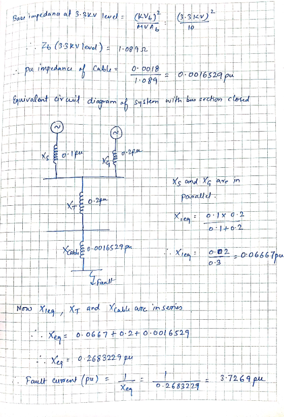
6. (i) For the system shown in FIGURE 4, determine the fault level for a fault on the cable at the 3.3 kV unit shown when the bus section switch is closed. The cable impedance is 90 microhms per metr...
Consider the 4-bus power system shown in Fig. 1. The system parameters are given below: 50 MVA, 2...
 Please show all the clearly step
Y11 ist j30 and Y44 isnt -j12.85
Consider the 4-bus power system shown in Fig. 1. The system parameters are given below: 50 MVA, 20 kV, X-2090 40 MVA, 20 kV, X-20%, X, = 5% 50 MVA, 20 kV Δ /110 kV Ý, X= 1090 50 MVA, 20 kV MI 10 kV Ý, X= 10% Xi-24.2 Ω Generator G: Motor M: Transformer T1 : Transformer T2 : Transmission line: 3 4 T2 nu)M Fig....
Please show all the clearly step
Y11 ist j30 and Y44 isnt -j12.85
Consider the 4-bus power system shown in Fig. 1. The system parameters are given below: 50 MVA, 20 kV, X-2090 40 MVA, 20 kV, X-20%, X, = 5% 50 MVA, 20 kV Δ /110 kV Ý, X= 1090 50 MVA, 20 kV MI 10 kV Ý, X= 10% Xi-24.2 Ω Generator G: Motor M: Transformer T1 : Transformer T2 : Transmission line: 3 4 T2 nu)M Fig....
Bus A Bus B R1 TI ine 1 20% 80% line 2 T2 R2 110 kV 11 kV The fault is located at point F, which ...
 Bus A Bus B R1 TI ine 1 20% 80% line 2 T2 R2 110 kV 11 kV The fault is located at point F, which is 20% of the total line 2 length from Bus B Fault MVA 1524.20471 Three-phase fault level in MVA at bus A SPFL (kA) 8 MVA1 MVA2 X1 (96 X2 (96) R1 (2) R2 (Q) z' (Q) Zo (2) Rf (Q) Single phase to ground fault level (kA) at bus A Transformer 1 MVA...
Bus A Bus B R1 T1 line 1 20% 80% line 2 T2 R2 110 kV 11 kV The fault is located at point F, which...
 Bus A Bus B R1 T1 line 1 20% 80% line 2 T2 R2 110 kV 11 kV The fault is located at point F, which is 20% of the total line 2 length from Bus B Fault MVA 1524.20471 Three-phase fault level in MVA at bus A SPFL (kA) 8 MVA1 MVA2 X1 (96) X2 (96) R1 (2) R2 (Q) z' (Q) Zo (2) Rf (Q) Single phase to ground fault level (kA) at bus A Transformer 1 MVA...
QUESTION 5 a) Define the Per Unit system and list three (3) main reasons of using Per Unit system...
 Per unit calculation
QUESTION 5 a) Define the Per Unit system and list three (3) main reasons of using Per Unit systemm. (5 marks) b) A three-bus power with two generator system is shown in figure Q2 (b). The 3-phase power and line-line voltage ratings are given below Ti T2 J40 2 Gi G2 j25 Ω 25 Ω Ty Figure Q2 (b) GI: 750 MVA, 18 kV, X 7% G2: 750 MVA, 18 kV, X-15% Motor: 1500 MVA, 20 kV,...
Per unit calculation
QUESTION 5 a) Define the Per Unit system and list three (3) main reasons of using Per Unit systemm. (5 marks) b) A three-bus power with two generator system is shown in figure Q2 (b). The 3-phase power and line-line voltage ratings are given below Ti T2 J40 2 Gi G2 j25 Ω 25 Ω Ty Figure Q2 (b) GI: 750 MVA, 18 kV, X 7% G2: 750 MVA, 18 kV, X-15% Motor: 1500 MVA, 20 kV,...
The one-line diagram of a simple power system is shown in Figure 1. The neutral of...
 The one-line diagram of a simple power system is shown in Figure 1. The neutral of each generator is grounded through a current-limiting reactor of 0.25/3 per unit on a 100-MVA base. The system data expressed in per unit on a common 100-MVA base is tabulated below. The generators are running on no-load at their rated voltage and rated frequency with their emfs in phase. Determine the fault current for the following faults giving Zo = 0.35, Z = 0.22...
A 7-bus power system with three generators, six transformers, and seven transmission lines is shown in...
 A 7-bus power system with three generators, six transformers, and seven transmission lines is shown in Figure Q1. The per-unit reactances for the generators and transfomers are based on their rated voltage and expressed in percentage. When a three-phase fault occurs at bus 5; three transmission lines, namely L4, L5, and L6, are disconnected from the power system. By taking the base apparent power of 100 MVA and the rated voltage of generator G1 as the reference, determine the per-unit...
The component parameters for the power system shown in Figure 2 are given in Table 1. The pre-fau...
 The component parameters for the power system shown in Figure 2 are given in Table 1. The pre-fault voltage is 120° pu and Zx-j0.1 pu. Table 1 Ratings X2-Xi (pu)Xo (pu) 0.05 0.10 0.20 0.20 Components G1, G2 200 MVA, 20 kV 0.10 0.10 0.10 0.10 T1, T2, T3200 MVA, 20/200 kV L1 200 MVA, 200 kV し2 200 MVA, 20 kV (a) Draw the three sequence networks and determine the per-unit Thevenin impedance of each sequence network seen from...
The one-line diagram of a three-bus power system is shown in Figure 4. All impedances are...
 The one-line diagram of a three-bus power system is shown in
Figure 4. All impedances are
expressed in per unit on a common MVA base. All resistances and
shunt capacitances are
neglected. Information on each component in this system is given
below:
• Each generator is represented by an emf
behind the sub-transient reactance of j0.045
and their neutrals are connected to the
ground.
• Line 1-2 has reactance of j0.88
• Line 2-3 has reactance of j0.65
• Line...
The one-line diagram of a three-bus power system is shown in
Figure 4. All impedances are
expressed in per unit on a common MVA base. All resistances and
shunt capacitances are
neglected. Information on each component in this system is given
below:
• Each generator is represented by an emf
behind the sub-transient reactance of j0.045
and their neutrals are connected to the
ground.
• Line 1-2 has reactance of j0.88
• Line 2-3 has reactance of j0.65
• Line...
2. A single-line diagram of the power system considered is shown in Figure P2a, where negative-...
 2. A single-line diagram of the power system considered is shown in Figure P2a, where negative- and zero-sequence reactances are also given. The neutrals of the generator and A-Y transformers are solidly grounded. The motor neutral is grounded through a reactance Xn = 0.05 per unit on the motor base. The per-unit zero-, positive and negative-sequence networks on a 100-MVA is shown in Figure P26, 13.8-kV base in the zone of the generator. a. Reduce the sequence networks to their...
 Please show all the clearly step
Y11 ist j30 and Y44 isnt -j12.85
Consider the 4-bus power system shown in Fig. 1. The system parameters are given below: 50 MVA, 20 kV, X-2090 40 MVA, 20 kV, X-20%, X, = 5% 50 MVA, 20 kV Δ /110 kV Ý, X= 1090 50 MVA, 20 kV MI 10 kV Ý, X= 10% Xi-24.2 Ω Generator G: Motor M: Transformer T1 : Transformer T2 : Transmission line: 3 4 T2 nu)M Fig....
Please show all the clearly step
Y11 ist j30 and Y44 isnt -j12.85
Consider the 4-bus power system shown in Fig. 1. The system parameters are given below: 50 MVA, 20 kV, X-2090 40 MVA, 20 kV, X-20%, X, = 5% 50 MVA, 20 kV Δ /110 kV Ý, X= 1090 50 MVA, 20 kV MI 10 kV Ý, X= 10% Xi-24.2 Ω Generator G: Motor M: Transformer T1 : Transformer T2 : Transmission line: 3 4 T2 nu)M Fig....
 Bus A Bus B R1 TI ine 1 20% 80% line 2 T2 R2 110 kV 11 kV The fault is located at point F, which is 20% of the total line 2 length from Bus B Fault MVA 1524.20471 Three-phase fault level in MVA at bus A SPFL (kA) 8 MVA1 MVA2 X1 (96 X2 (96) R1 (2) R2 (Q) z' (Q) Zo (2) Rf (Q) Single phase to ground fault level (kA) at bus A Transformer 1 MVA...
 Bus A Bus B R1 TI ine 1 20% 80% line 2 T2 R2 110 kV 11 kV The fault is located at point F, which is 20% of the total line 2 length from Bus B Fault MVA 1524.20471 Three-phase fault level in MVA at bus A SPFL (kA) 8 MVA1 MVA2 X1 (96 X2 (96) R1 (2) R2 (Q) z' (Q) Zo (2) Rf (Q) Single phase to ground fault level (kA) at bus A Transformer 1 MVA...
 Bus A Bus B R1 T1 line 1 20% 80% line 2 T2 R2 110 kV 11 kV The fault is located at point F, which is 20% of the total line 2 length from Bus B Fault MVA 1524.20471 Three-phase fault level in MVA at bus A SPFL (kA) 8 MVA1 MVA2 X1 (96) X2 (96) R1 (2) R2 (Q) z' (Q) Zo (2) Rf (Q) Single phase to ground fault level (kA) at bus A Transformer 1 MVA...
 Per unit calculation
QUESTION 5 a) Define the Per Unit system and list three (3) main reasons of using Per Unit systemm. (5 marks) b) A three-bus power with two generator system is shown in figure Q2 (b). The 3-phase power and line-line voltage ratings are given below Ti T2 J40 2 Gi G2 j25 Ω 25 Ω Ty Figure Q2 (b) GI: 750 MVA, 18 kV, X 7% G2: 750 MVA, 18 kV, X-15% Motor: 1500 MVA, 20 kV,...
Per unit calculation
QUESTION 5 a) Define the Per Unit system and list three (3) main reasons of using Per Unit systemm. (5 marks) b) A three-bus power with two generator system is shown in figure Q2 (b). The 3-phase power and line-line voltage ratings are given below Ti T2 J40 2 Gi G2 j25 Ω 25 Ω Ty Figure Q2 (b) GI: 750 MVA, 18 kV, X 7% G2: 750 MVA, 18 kV, X-15% Motor: 1500 MVA, 20 kV,...
 The one-line diagram of a simple power system is shown in Figure 1. The neutral of each generator is grounded through a current-limiting reactor of 0.25/3 per unit on a 100-MVA base. The system data expressed in per unit on a common 100-MVA base is tabulated below. The generators are running on no-load at their rated voltage and rated frequency with their emfs in phase. Determine the fault current for the following faults giving Zo = 0.35, Z = 0.22...
 A 7-bus power system with three generators, six transformers, and seven transmission lines is shown in Figure Q1. The per-unit reactances for the generators and transfomers are based on their rated voltage and expressed in percentage. When a three-phase fault occurs at bus 5; three transmission lines, namely L4, L5, and L6, are disconnected from the power system. By taking the base apparent power of 100 MVA and the rated voltage of generator G1 as the reference, determine the per-unit...
 The component parameters for the power system shown in Figure 2 are given in Table 1. The pre-fault voltage is 120° pu and Zx-j0.1 pu. Table 1 Ratings X2-Xi (pu)Xo (pu) 0.05 0.10 0.20 0.20 Components G1, G2 200 MVA, 20 kV 0.10 0.10 0.10 0.10 T1, T2, T3200 MVA, 20/200 kV L1 200 MVA, 200 kV し2 200 MVA, 20 kV (a) Draw the three sequence networks and determine the per-unit Thevenin impedance of each sequence network seen from...
 The one-line diagram of a three-bus power system is shown in
Figure 4. All impedances are
expressed in per unit on a common MVA base. All resistances and
shunt capacitances are
neglected. Information on each component in this system is given
below:
• Each generator is represented by an emf
behind the sub-transient reactance of j0.045
and their neutrals are connected to the
ground.
• Line 1-2 has reactance of j0.88
• Line 2-3 has reactance of j0.65
• Line...
The one-line diagram of a three-bus power system is shown in
Figure 4. All impedances are
expressed in per unit on a common MVA base. All resistances and
shunt capacitances are
neglected. Information on each component in this system is given
below:
• Each generator is represented by an emf
behind the sub-transient reactance of j0.045
and their neutrals are connected to the
ground.
• Line 1-2 has reactance of j0.88
• Line 2-3 has reactance of j0.65
• Line...
 2. A single-line diagram of the power system considered is shown in Figure P2a, where negative- and zero-sequence reactances are also given. The neutrals of the generator and A-Y transformers are solidly grounded. The motor neutral is grounded through a reactance Xn = 0.05 per unit on the motor base. The per-unit zero-, positive and negative-sequence networks on a 100-MVA is shown in Figure P26, 13.8-kV base in the zone of the generator. a. Reduce the sequence networks to their...
Most questions answered within 3 hours.
-
Kylie is a single mom with two dependent children,
Tanner, age 7 and Olivia, age 11....
asked 45 minutes ago -
Phosphorous + bromine = phosphorous tribromide. If 35.0 g of
bromine are reacted and 27.9 grams...
asked 2 hours ago -
Derive the long wavelength limit of the Planck energy density
distribution
asked 2 hours ago -
Calculate the pH of each of the following solutions.
0.50 M HBr
3.1×10⁻⁴ M KOH
4.2×10⁻⁵...
asked 5 hours ago -
For the year ended December 31, Depot Max’s cost of merchandise
sold was $85,600. Inventory at the...
asked 5 hours ago -
Week 10 - Professional Memo Assignment
Professional Memo Assignment
Your mission for this week, should you...
asked 5 hours ago -
Write a Python program that stores the data for each
player on the team, and it...
asked 5 hours ago -
In
the last 3 months, mike never knows when he is going to get his
allowance...
asked 6 hours ago -
Is Ca(OH)2 a Bronsted base, Lewis base, or both? Why?
asked 6 hours ago -
1A- Why don’t voters complain about U.S. tariffs on imported
sugar?
Because sugar is only a...
asked 6 hours ago -
Cash Payback Period
Primera Banco is evaluating two capital investment proposals for
a drive-up ATM kiosk,...
asked 6 hours ago -
Create a button in Swift (Xcode) that will create a charge,
create a charge using Stripe's...
asked 6 hours ago