
Homework Answers

And here is the simulation part

Please thumbs up if you find the answer helpful
Add Answer to:
Please solve this ASAP. You are to design an op-amp based amplifier that generates the following transfer function Vref Task: Design an op-amp based amplifier that obeys the above function. Make sure...
need help for d,e,f OP-Amp Circuit R-20k Fig 1 1. Design an operational amplifier circuit using an LM741 op-amp an...
 need help for d,e,f
OP-Amp Circuit R-20k Fig 1 1. Design an operational amplifier circuit using an LM741 op-amp and a 10k the diagram shown in Fig 1 to produce the output voltage feedback resistor that represents Clearly write your ID number in Table 1 Table 1 Your ID Number 3775。73 . Set up the roquired gain numbers as follows and write them in Table 2 Ai- the last digit of your ID number+5 A2-the 2ed last digit of your...
need help for d,e,f
OP-Amp Circuit R-20k Fig 1 1. Design an operational amplifier circuit using an LM741 op-amp and a 10k the diagram shown in Fig 1 to produce the output voltage feedback resistor that represents Clearly write your ID number in Table 1 Table 1 Your ID Number 3775。73 . Set up the roquired gain numbers as follows and write them in Table 2 Ai- the last digit of your ID number+5 A2-the 2ed last digit of your...
Build an Op-Amp Circuit Network. Note you only have a power source of 5V available. You...
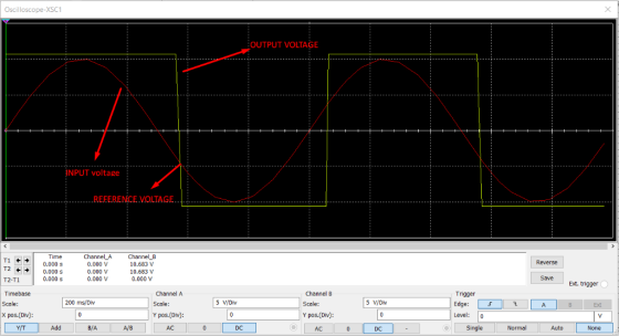
Build an Op-Amp Circuit Network. Note you only have a power source of 5V available. You have a voltage signal that latches at a constant 1.5V. Create a difference circuit to produce an output voltage of 2V. Put P/Ns and element values in your design. Show your work. From part a)’s output voltage, assign that now as a reference voltage (Vref) to compare to an analog sensor signal (Vin) that can range between 0V – 5V. Make sure your circuit...
Problem 3: Design Problem On Figure P3a, you have a Common Source (CS) n-channel MOSFET amplifier....
 Problem 3: Design Problem On Figure P3a, you have a Common Source (CS) n-channel MOSFET amplifier. Notice the absence of a source resistor Rsig and load resistor R. If we know how the present amplifier (the one on Figure P3a) behaves without Rsig and RL, we can infer its behaviors if Rsig and R were to be added. design the amplifier circuit on Figure P3a, i.e., you have to find appropriate values for RGj You are to RG,, RD, and...
Simulation For each filter mentioned in the following cases, first simulate the circuit using Multisim. You can get a plot of the transfer function that is called the Bode plot. From the right toolba...
 Simulation For each filter mentioned in the following cases, first simulate the circuit using Multisim. You can get a plot of the transfer function that is called the Bode plot. From the right toolbar, select "Bode Plotter". Change initial (I) and final (F) frequencies to 1Hz and 200 KHz, respectively. Use a Voltage AC source as the input signal. You do not need to change any parameter from voltage AC source. Connect "Bode Plotter" to input and output of your...
For each filter mentioned in the following cases, first simulate the circuit using Multisim. You can get a plot of the transfer function that is called the Bode plot. From the right toolbar, select &...
 For each filter mentioned in the following cases, first simulate the circuit using Multisim. You can get a plot of the transfer function that is called the Bode plot. From the right toolbar, select "Bode Plotter". Change initial (I) and final (F frequencies to 1Hz and 200 KHz, respectively. Use a Voltage AC source as the input signal. You do not need to change any parameter from voltage AC source Connect "Bode Plotter" to input and output of your circuit...
A common source amplifier circuit based on a single n-channel MOSFET is shown in Figure 4b. Assume that the transconductance gm-60 mS (equivalent to mA/ V) and drain source resistance, os,...
 A common source amplifier circuit based on a single n-channel MOSFET is shown in Figure 4b. Assume that the transconductance gm-60 mS (equivalent to mA/ V) and drain source resistance, os, is so large it may be neglected. 0) Calculate the open circuit voltage gain Av Yout/ Vis. i) The amplifier has a load of 10 k2. Determine the current gain Va. = 12 V 150k 4k3 Vout Vin 200k GND = 0 V Figure 4b a) State the name...
Vout should be a sinusoid signal of 12Vp-p Dc voltage to uA741 : +/-8.5V Please simulate...
 Vout should be a sinusoid signal of 12Vp-p
Dc voltage to uA741 : +/-8.5V
Please simulate as well
please help, im completely lost on this
this is all of the information
Experiment 5. RC Sinusoidal Oscillators PURPOSE: This laboratory provides an introduction to the background, analysis and design of sinusoidal oscillators using RC feedback networks and active devices to achieve the criteria for continuous oscillations to occur. EQUIPMENT REQUIRED : 1 Operational amplifier u.A741 1 CEU development station Resistors and...
Vout should be a sinusoid signal of 12Vp-p
Dc voltage to uA741 : +/-8.5V
Please simulate as well
please help, im completely lost on this
this is all of the information
Experiment 5. RC Sinusoidal Oscillators PURPOSE: This laboratory provides an introduction to the background, analysis and design of sinusoidal oscillators using RC feedback networks and active devices to achieve the criteria for continuous oscillations to occur. EQUIPMENT REQUIRED : 1 Operational amplifier u.A741 1 CEU development station Resistors and...
How can we assess whether a project is a success or a failure? This case presents...
 How can we assess whether a project is a success or a
failure?
This case presents two phases of a large business transformation project involving the implementation of an ERP system with the aim of creating an integrated company. The case illustrates some of the challenges associated with integration. It also presents the obstacles facing companies that undertake projects involving large information technology projects. Bombardier and Its Environment Joseph-Armand Bombardier was 15 years old when he built his first snowmobile...
How can we assess whether a project is a success or a
failure?
This case presents two phases of a large business transformation project involving the implementation of an ERP system with the aim of creating an integrated company. The case illustrates some of the challenges associated with integration. It also presents the obstacles facing companies that undertake projects involving large information technology projects. Bombardier and Its Environment Joseph-Armand Bombardier was 15 years old when he built his first snowmobile...
 need help for d,e,f
OP-Amp Circuit R-20k Fig 1 1. Design an operational amplifier circuit using an LM741 op-amp and a 10k the diagram shown in Fig 1 to produce the output voltage feedback resistor that represents Clearly write your ID number in Table 1 Table 1 Your ID Number 3775。73 . Set up the roquired gain numbers as follows and write them in Table 2 Ai- the last digit of your ID number+5 A2-the 2ed last digit of your...
need help for d,e,f
OP-Amp Circuit R-20k Fig 1 1. Design an operational amplifier circuit using an LM741 op-amp and a 10k the diagram shown in Fig 1 to produce the output voltage feedback resistor that represents Clearly write your ID number in Table 1 Table 1 Your ID Number 3775。73 . Set up the roquired gain numbers as follows and write them in Table 2 Ai- the last digit of your ID number+5 A2-the 2ed last digit of your...
 Problem 3: Design Problem On Figure P3a, you have a Common Source (CS) n-channel MOSFET amplifier. Notice the absence of a source resistor Rsig and load resistor R. If we know how the present amplifier (the one on Figure P3a) behaves without Rsig and RL, we can infer its behaviors if Rsig and R were to be added. design the amplifier circuit on Figure P3a, i.e., you have to find appropriate values for RGj You are to RG,, RD, and...
 Simulation For each filter mentioned in the following cases, first simulate the circuit using Multisim. You can get a plot of the transfer function that is called the Bode plot. From the right toolbar, select "Bode Plotter". Change initial (I) and final (F) frequencies to 1Hz and 200 KHz, respectively. Use a Voltage AC source as the input signal. You do not need to change any parameter from voltage AC source. Connect "Bode Plotter" to input and output of your...
 For each filter mentioned in the following cases, first simulate the circuit using Multisim. You can get a plot of the transfer function that is called the Bode plot. From the right toolbar, select "Bode Plotter". Change initial (I) and final (F frequencies to 1Hz and 200 KHz, respectively. Use a Voltage AC source as the input signal. You do not need to change any parameter from voltage AC source Connect "Bode Plotter" to input and output of your circuit...
 A common source amplifier circuit based on a single n-channel MOSFET is shown in Figure 4b. Assume that the transconductance gm-60 mS (equivalent to mA/ V) and drain source resistance, os, is so large it may be neglected. 0) Calculate the open circuit voltage gain Av Yout/ Vis. i) The amplifier has a load of 10 k2. Determine the current gain Va. = 12 V 150k 4k3 Vout Vin 200k GND = 0 V Figure 4b a) State the name...
 Vout should be a sinusoid signal of 12Vp-p
Dc voltage to uA741 : +/-8.5V
Please simulate as well
please help, im completely lost on this
this is all of the information
Experiment 5. RC Sinusoidal Oscillators PURPOSE: This laboratory provides an introduction to the background, analysis and design of sinusoidal oscillators using RC feedback networks and active devices to achieve the criteria for continuous oscillations to occur. EQUIPMENT REQUIRED : 1 Operational amplifier u.A741 1 CEU development station Resistors and...
Vout should be a sinusoid signal of 12Vp-p
Dc voltage to uA741 : +/-8.5V
Please simulate as well
please help, im completely lost on this
this is all of the information
Experiment 5. RC Sinusoidal Oscillators PURPOSE: This laboratory provides an introduction to the background, analysis and design of sinusoidal oscillators using RC feedback networks and active devices to achieve the criteria for continuous oscillations to occur. EQUIPMENT REQUIRED : 1 Operational amplifier u.A741 1 CEU development station Resistors and...
 How can we assess whether a project is a success or a
failure?
This case presents two phases of a large business transformation project involving the implementation of an ERP system with the aim of creating an integrated company. The case illustrates some of the challenges associated with integration. It also presents the obstacles facing companies that undertake projects involving large information technology projects. Bombardier and Its Environment Joseph-Armand Bombardier was 15 years old when he built his first snowmobile...
How can we assess whether a project is a success or a
failure?
This case presents two phases of a large business transformation project involving the implementation of an ERP system with the aim of creating an integrated company. The case illustrates some of the challenges associated with integration. It also presents the obstacles facing companies that undertake projects involving large information technology projects. Bombardier and Its Environment Joseph-Armand Bombardier was 15 years old when he built his first snowmobile...
Most questions answered within 3 hours.
-
Assume that capital markets are competitive and that the
international Fisher hypothesis holds. The one-year interest...
asked 24 minutes ago -
Solid potassium phosphate is slowly added to 150 mL of a 0.0518
M calcium nitrate solution....
asked 38 minutes ago -
(CO 2) A field can be added to a report to
values for two or more...
asked 2 hours ago -
Identify 3 research scenarios that might provide a low,
medium, and high degree of variability in...
asked 2 hours ago -
how
does gravity affect the trajectory of projectile? what would be the
shape of the trajactory...
asked 3 hours ago -
Two small plastic spheres are given positive electrical charges.
When they are a distance of 15.4...
asked 3 hours ago -
An acidic solution containing gold ions is
electrolyzed, producing gaseous oxygen (from water) at the anode...
asked 4 hours ago -
Assume that the population of Mexico is 128
million and that the population increases 1.01
percentannually....
asked 5 hours ago -
Can someone please help me add appropriate descriptive
comments to each line of code in the...
asked 5 hours ago -
Romeo wishes to throw a bouquet of flowers to Juliet, who is on
a second-story balcony,...
asked 6 hours ago -
Why is QE a controversial monetary policy tool.
A. It may lead to excessive inflation.B. By...
asked 6 hours ago -
Principles of Programming midterm study guide help!
1.)
______ Which of the following would reference the...
asked 5 hours ago