
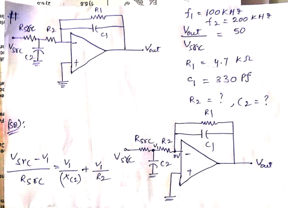
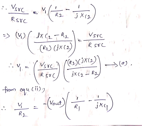
is it ok to use R1=4.7Kohms and C1=330pf? And I want to know how to calculate the R2, Rsrc, and C2
Homework Answers


Add Answer to:
is it ok to use R1=4.7Kohms and C1=330pf? And I want to know how to calculate the R2, Rsrc, and C2 tage 2:Baseband Filt...
For the low-pass filter circuit shown in Fig 2 3k Ω 200mil in out Fig 2 3.a. Use a 2.2nF capacitor to design a high-pas...
 For the low-pass filter circuit shown in Fig 2 3k Ω 200mil in out Fig 2 3.a. Use a 2.2nF capacitor to design a high-pass filter to have a cutoff frequency of Skn Draw a schematic of your design. Show all component values and voltages c. Sketch the frequency response of the voltage gain and phase shift Magnitude dB Frequency Hz Phase Frequency Hz
For the low-pass filter circuit shown in Fig 2 3k Ω 200mil in out Fig 2...
For the low-pass filter circuit shown in Fig 2 3k Ω 200mil in out Fig 2 3.a. Use a 2.2nF capacitor to design a high-pass filter to have a cutoff frequency of Skn Draw a schematic of your design. Show all component values and voltages c. Sketch the frequency response of the voltage gain and phase shift Magnitude dB Frequency Hz Phase Frequency Hz
For the low-pass filter circuit shown in Fig 2 3k Ω 200mil in out Fig 2...
Filter VC Filter 2 vCC VccPeak Detector VCC R3 R13 47:C1 U2 VCC vcc RT 0.1uFRS VM 10040 03 741 R1...
 Filter VC Filter 2 vCC VccPeak Detector VCC R3 R13 47:C1 U2 VCC vcc RT 0.1uFRS VM 10040 03 741 R12 C2 .01uF L1 VEE 74 R10 VEVEE R12 15.0V VCC R8 R2 2010: 85 % ko Co Input and 1st Gain Stage: What is the function of the RC configuration of Filter 1? What is the function of the first op-amp, U2? Band Pass Filter: What is the function of the band-pass filter of Filter 2? What is your...
Project Requirements: 1. Based on the schematic approach indicated below, determine capacitances Cl and C2 and...
 Project Requirements: 1. Based on the schematic approach indicated below, determine capacitances Cl and C2 and an ideal OP AMP configuration that will result in a band pass circuit having a maximum gain of 12 dB with -3dB frequencies at 10 Hz and 2000 Hz The OP AMP circuit should not produce any phase shift. In the OP AMP circuit don't use any discrete resistor values less than K2. In this design, Ti(s) is to be the transfer function of...
Derive the transfer function of the circuit in Fig.P2.93(foranidealopamp)andshowthatitcanbewritten in the form Vo Vi = −R2/R1...
 Derive the transfer function of the circuit in
Fig.P2.93(foranidealopamp)andshowthatitcanbewritten in the
form
Vo Vi = −R2/R1 [1+(ω1/jω)][1+j(ω/ω2)] whereω1=1/C1R1
andω2=1/C2R2.Assumingthatthecircuit is designed such that ω2 ω1,
find approximate expressions
for the transfer function in the following frequency regions: (a)
ωω1 (b) ω1 ωω2 (c) ωω2
Vo
FigureP2.93
Use these approximations to sketch a Bode plot for the magnitude
response. Observe that the circuit performs as an amplifier whose
gain rolls off at the low-frequency end in the manner of a
high-pass...
Derive the transfer function of the circuit in
Fig.P2.93(foranidealopamp)andshowthatitcanbewritten in the
form
Vo Vi = −R2/R1 [1+(ω1/jω)][1+j(ω/ω2)] whereω1=1/C1R1
andω2=1/C2R2.Assumingthatthecircuit is designed such that ω2 ω1,
find approximate expressions
for the transfer function in the following frequency regions: (a)
ωω1 (b) ω1 ωω2 (c) ωω2
Vo
FigureP2.93
Use these approximations to sketch a Bode plot for the magnitude
response. Observe that the circuit performs as an amplifier whose
gain rolls off at the low-frequency end in the manner of a
high-pass...
Notes you have to use MathLab No Hand Writing and Write answer by typing PDF Or document word.
 Notes you have to use
MathLab
No Hand Writing
and Write answer by typing
PDF Or document word.
Active 1st Order Filters Objective An active filter is a type of analog electronic filter distinguished by the use of one or more active components. Typically this will be a yacuum tube, or solid-state Active filters have three main advantages over passive filters: Inductors can be avoided. Passive filters without inductors cannot obtain a high Q (low damping), but with them are...
Notes you have to use
MathLab
No Hand Writing
and Write answer by typing
PDF Or document word.
Active 1st Order Filters Objective An active filter is a type of analog electronic filter distinguished by the use of one or more active components. Typically this will be a yacuum tube, or solid-state Active filters have three main advantages over passive filters: Inductors can be avoided. Passive filters without inductors cannot obtain a high Q (low damping), but with them are...
Laboratory 1: operation amplifier characteristics A. Objectives: 1. To study the basic characteri...
 thanks
Laboratory 1: operation amplifier characteristics A. Objectives: 1. To study the basic characteristics of an operational amplifier 2. To study the bias circuit of an operational amplifier B. Apparatus: 1. DC Power supply 2. Experimental board and corresponding components 3. Electronic calculator (prepared by students) 4. Digital camera (prepared by students for photo taking of the experimental results) 5. Laptop computer with the software PicoScope 6 and Microsoft Word installed. 6. PicoScope PC Oscilloscope and its accessories. 7. Multimeter...
thanks
Laboratory 1: operation amplifier characteristics A. Objectives: 1. To study the basic characteristics of an operational amplifier 2. To study the bias circuit of an operational amplifier B. Apparatus: 1. DC Power supply 2. Experimental board and corresponding components 3. Electronic calculator (prepared by students) 4. Digital camera (prepared by students for photo taking of the experimental results) 5. Laptop computer with the software PicoScope 6 and Microsoft Word installed. 6. PicoScope PC Oscilloscope and its accessories. 7. Multimeter...
 For the low-pass filter circuit shown in Fig 2 3k Ω 200mil in out Fig 2 3.a. Use a 2.2nF capacitor to design a high-pass filter to have a cutoff frequency of Skn Draw a schematic of your design. Show all component values and voltages c. Sketch the frequency response of the voltage gain and phase shift Magnitude dB Frequency Hz Phase Frequency Hz
For the low-pass filter circuit shown in Fig 2 3k Ω 200mil in out Fig 2...
For the low-pass filter circuit shown in Fig 2 3k Ω 200mil in out Fig 2 3.a. Use a 2.2nF capacitor to design a high-pass filter to have a cutoff frequency of Skn Draw a schematic of your design. Show all component values and voltages c. Sketch the frequency response of the voltage gain and phase shift Magnitude dB Frequency Hz Phase Frequency Hz
For the low-pass filter circuit shown in Fig 2 3k Ω 200mil in out Fig 2...
 Filter VC Filter 2 vCC VccPeak Detector VCC R3 R13 47:C1 U2 VCC vcc RT 0.1uFRS VM 10040 03 741 R12 C2 .01uF L1 VEE 74 R10 VEVEE R12 15.0V VCC R8 R2 2010: 85 % ko Co Input and 1st Gain Stage: What is the function of the RC configuration of Filter 1? What is the function of the first op-amp, U2? Band Pass Filter: What is the function of the band-pass filter of Filter 2? What is your...
 Project Requirements: 1. Based on the schematic approach indicated below, determine capacitances Cl and C2 and an ideal OP AMP configuration that will result in a band pass circuit having a maximum gain of 12 dB with -3dB frequencies at 10 Hz and 2000 Hz The OP AMP circuit should not produce any phase shift. In the OP AMP circuit don't use any discrete resistor values less than K2. In this design, Ti(s) is to be the transfer function of...
 Derive the transfer function of the circuit in
Fig.P2.93(foranidealopamp)andshowthatitcanbewritten in the
form
Vo Vi = −R2/R1 [1+(ω1/jω)][1+j(ω/ω2)] whereω1=1/C1R1
andω2=1/C2R2.Assumingthatthecircuit is designed such that ω2 ω1,
find approximate expressions
for the transfer function in the following frequency regions: (a)
ωω1 (b) ω1 ωω2 (c) ωω2
Vo
FigureP2.93
Use these approximations to sketch a Bode plot for the magnitude
response. Observe that the circuit performs as an amplifier whose
gain rolls off at the low-frequency end in the manner of a
high-pass...
Derive the transfer function of the circuit in
Fig.P2.93(foranidealopamp)andshowthatitcanbewritten in the
form
Vo Vi = −R2/R1 [1+(ω1/jω)][1+j(ω/ω2)] whereω1=1/C1R1
andω2=1/C2R2.Assumingthatthecircuit is designed such that ω2 ω1,
find approximate expressions
for the transfer function in the following frequency regions: (a)
ωω1 (b) ω1 ωω2 (c) ωω2
Vo
FigureP2.93
Use these approximations to sketch a Bode plot for the magnitude
response. Observe that the circuit performs as an amplifier whose
gain rolls off at the low-frequency end in the manner of a
high-pass...
 Notes you have to use
MathLab
No Hand Writing
and Write answer by typing
PDF Or document word.
Active 1st Order Filters Objective An active filter is a type of analog electronic filter distinguished by the use of one or more active components. Typically this will be a yacuum tube, or solid-state Active filters have three main advantages over passive filters: Inductors can be avoided. Passive filters without inductors cannot obtain a high Q (low damping), but with them are...
Notes you have to use
MathLab
No Hand Writing
and Write answer by typing
PDF Or document word.
Active 1st Order Filters Objective An active filter is a type of analog electronic filter distinguished by the use of one or more active components. Typically this will be a yacuum tube, or solid-state Active filters have three main advantages over passive filters: Inductors can be avoided. Passive filters without inductors cannot obtain a high Q (low damping), but with them are...
 thanks
Laboratory 1: operation amplifier characteristics A. Objectives: 1. To study the basic characteristics of an operational amplifier 2. To study the bias circuit of an operational amplifier B. Apparatus: 1. DC Power supply 2. Experimental board and corresponding components 3. Electronic calculator (prepared by students) 4. Digital camera (prepared by students for photo taking of the experimental results) 5. Laptop computer with the software PicoScope 6 and Microsoft Word installed. 6. PicoScope PC Oscilloscope and its accessories. 7. Multimeter...
thanks
Laboratory 1: operation amplifier characteristics A. Objectives: 1. To study the basic characteristics of an operational amplifier 2. To study the bias circuit of an operational amplifier B. Apparatus: 1. DC Power supply 2. Experimental board and corresponding components 3. Electronic calculator (prepared by students) 4. Digital camera (prepared by students for photo taking of the experimental results) 5. Laptop computer with the software PicoScope 6 and Microsoft Word installed. 6. PicoScope PC Oscilloscope and its accessories. 7. Multimeter...
Most questions answered within 3 hours.
-
A consumer can choose between two gambles. The “sure thing”
guaranteesadditional income (I) of $250,000. The...
asked 2 minutes from now -
There are 9 women and 6 men in a department. A committee of four
is to...
asked 8 seconds from now -
Arthur Meiners is the production manager of Wheel-Rite, a small
producer of metal parts. Wheel-Rite supplies...
asked 14 minutes ago -
Company Risk Premium A company has a beta of
4.57. If the market return is expected...
asked 13 minutes ago -
3. Which statement about nuclear fission is correct? (1
point)
A. Nuclear fission provides energy for...
asked 19 minutes ago -
If a $2,000 increase in income leads to a $1,5000 increase in
consumption expenditures, then the...
asked 18 minutes ago -
May you please put this in layman's terms?
ABSTRACT
Coagulase-negative staphylococci (CoNS) and Staphylococcus
aureus are...
asked 23 minutes ago -
If authentic leadership is really a lifelong process,
can teenagers be authentic leaders? Why or why...
asked 39 minutes ago -
Six years of quarterly data of a seasonally adjusted series are
used to estimate a linear...
asked 57 minutes ago -
Which of the following is not an ecological model used
to foster behavior change?
PRECEDE-PROCEED Model...
asked 1 hour ago -
On the Apollo 14 mission to the moon, astronaut Alan Shepard hit
a golf ball with...
asked 57 minutes ago -
What are John’s potential claims if he is terminated
this week?
John is a 54-year-old man...
asked 1 hour ago