
Homework Answers
`Hey,
Note: Brother in case of any queries, just comment in box I would be very happy to assist all your queries
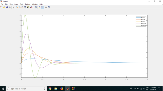
clear, clc
KV=[10,26,40,100,200];
syms s t
for i=1:length(KV)
K=KV(i);
fprintf('For K=%d, th(s)=\n',K);
K/(s^2+10*s+K)
f=matlabFunction(ilaplace(K/(s^2+10*s+K),s,t));
fplot(f,[0,3]);
hold on;
end
hold off;
legend('K=10','K=26','K=50','K=100','K=200')
Kindly revert for any queries
Thanks.
Add Answer to:
System Description A video camera system, similar to that shown in figure below, can automatically follow a subject. Th...
4.) (a) Sketch the positive root locus of the system shown below using the (2, 2) Pade approximat...
 4.) (a) Sketch the positive root locus of the system shown below using the (2, 2) Pade approximation for the delay. State the asymptote angles and their centroid, the arrival and departure angles at any complex pole or zero, the frequencies of any imaginary axis crossings, and the locations of any break-in or break-away points. (b) Use Matlab to plot the positive root locus of the system shown below using the (2, 2) Pade approximation for the delay. Your sketch...
Problem 51: (25 points) Figure 5 is an example of a feedback control system that is designed to r...
 Problem 51: (25 points) Figure 5 is an example of a feedback control system that is designed to regulate the angular position θ(t) of a motor shaft to a desired value θr(t). The signal e(t) represents the error between the measured shaft angle θ(t) and the desired shaft angle θ (t). The Laplace transforms ofa,(t), θ(t), and e(t) are denoted as ΘR(s), θ(s), and E(s), respectively. The control gains Ki and K2 are chosen by the control engineer to achieve...
2. For the simple pendulum shown in Figure 2, the nonlinear equations of motion are given by θ(t)...
 do (b) and (c) only.
2. For the simple pendulum shown in Figure 2, the nonlinear equations of motion are given by θ(t) + 믈 sin θ(t) + m 0(t)-0 Pivot point L, length Massless rod , mass Figure 2. A simple pendulum 3. Consider again the pendulum of Figure 2 of problem 2 when g = 9.8 m/s, 1 = 4.9m, k =0.3, and (a) Determine whether the system is stable by finding the characteristic equation obtained from setting...
do (b) and (c) only.
2. For the simple pendulum shown in Figure 2, the nonlinear equations of motion are given by θ(t) + 믈 sin θ(t) + m 0(t)-0 Pivot point L, length Massless rod , mass Figure 2. A simple pendulum 3. Consider again the pendulum of Figure 2 of problem 2 when g = 9.8 m/s, 1 = 4.9m, k =0.3, and (a) Determine whether the system is stable by finding the characteristic equation obtained from setting...
PROBLEM 4 Suppose that a system is shown in Figure 4. There are three controllers that might be incorporated into this system. 1. Ge (s)-K (proportional (P) controller) 2. GS)K/s (integral (I) contro...
 PROBLEM 4 Suppose that a system is shown in Figure 4. There are three controllers that might be incorporated into this system. 1. Ge (s)-K (proportional (P) controller) 2. GS)K/s (integral (I) controller) 3. G (s)K(1+1/s) (proportional, integral (PI) controller) The system requirements are T, < 10 seconds and P0 10% for a unit step response. (a) For the (P) controller, write a piece of MATLAB code to plot root locus for 0<K<,and find the K value so that the...
winkngs spring i(t) v(t) st VEE Figure 1: (a)Solenoid with retu spring. (b) Equivalent lumped electrical cireuit (...
 winkngs spring i(t) v(t) st VEE Figure 1: (a)Solenoid with retu spring. (b) Equivalent lumped electrical cireuit (e) Equivalent mechanical diagram Figure 1(a) illustrates a solenoid with a return spring The voltage e(t) across the winding, causes a current it) to flow through the winding. which in turn generates a magnetic field The magnetic field induces a force f(t) on the plunger mass, . The magnitude of this force is related to the current in the windings via the solenoid's...
Consider the electromechanical dynamic system shown in Figure 1(a). It consists of a cart of mass...
 This assignment is for my Engr dynamics systems class.
Consider the electromechanical dynamic system shown in Figure 1(a). It consists of a cart of mass m moving without slipping on a linear ground track. The cart is equipped with an armature-controlled DC motor, which is coupled to a rack and pinion mechanism to convert the rotational motion to translation and to create the driving force for the system. Figure 1(b) shows the simplified equivalent electric circuit and the mechanical model...
This assignment is for my Engr dynamics systems class.
Consider the electromechanical dynamic system shown in Figure 1(a). It consists of a cart of mass m moving without slipping on a linear ground track. The cart is equipped with an armature-controlled DC motor, which is coupled to a rack and pinion mechanism to convert the rotational motion to translation and to create the driving force for the system. Figure 1(b) shows the simplified equivalent electric circuit and the mechanical model...
Consider the automobile cruise-control system shown below: Engine ActuatorCarburetor 0.833 and load 40 3s +1 Compensator R(s)E(s) Ge(s) s +1 -t e(t) Sensor 0.03 1) Derive the closed-loop transfer fun...
 Consider the automobile cruise-control system shown below: Engine ActuatorCarburetor 0.833 and load 40 3s +1 Compensator R(s)E(s) Ge(s) s +1 -t e(t) Sensor 0.03 1) Derive the closed-loop transfer function of V(s)/R(s) when Gc(s)-1 2) Derive the closed-loop transfer function of E(s)/R(s) when Ge(s)-1 3) Plot the time history of the error e(t) of the closed-loop system when r(t) is a unit step input. 4) Plot the root-loci of the uncompensated system (when Gc(s)-1). Mark the closed-loop complex poles on...
3.2 Pre-Lab Assignment When deriving the governing equations for an electromechanical system, it is often beneficial...
 3.2 Pre-Lab Assignment When deriving the governing equations for an electromechanical system, it is often beneficial to examine the electrical and mechanical components independently. Looking at only the electrical components of the QUBE-Servo DC motor (as shown in Figure 3.2): R v00 C e, (00 Figure 3.2: Electrical curcuit of the QUBE-Servo DC motor Q1. Write the differential equation in the form of Kirchoff's voltage law) in the Laplace domain for the electrical circuit (do not use parameter values given...
#5 is only I need in which we need to plot it on Matlab and I...
 #5 is only I need in which we need to plot it on Matlab
and I don't know how to plot it.
Project 1 A Vibration Insulation Problem Passive isolation systems are sometimes used to insulate delicate equipment from unwanted vibrations. For example, in order to insulate electrical monitoring equipment from vibrations present in the floor of an industrial plant, the equipment may be placed on a platform supported by flexible mountings resting on the floor. A simple physical model...
#5 is only I need in which we need to plot it on Matlab
and I don't know how to plot it.
Project 1 A Vibration Insulation Problem Passive isolation systems are sometimes used to insulate delicate equipment from unwanted vibrations. For example, in order to insulate electrical monitoring equipment from vibrations present in the floor of an industrial plant, the equipment may be placed on a platform supported by flexible mountings resting on the floor. A simple physical model...
Seismometer Project Imagine that we have a delicate instrument carefully mounted on a low-friction surface, and...
 Seismometer Project Imagine that we have a delicate instrument carefully mounted on a low-friction surface, and held in place laterally by springs. Delicate Instrument Very low friction Mounting frame fixed to Earth Since the mounting frame is fixed to the Earth, seismic movements such as earthquakes are our input into the system! The delicate instrument of mass 'm', on the other hand, wants to stay fixed relative to inertial space. Let's assume that the inertial position of the delicate instrument...
 4.) (a) Sketch the positive root locus of the system shown below using the (2, 2) Pade approximation for the delay. State the asymptote angles and their centroid, the arrival and departure angles at any complex pole or zero, the frequencies of any imaginary axis crossings, and the locations of any break-in or break-away points. (b) Use Matlab to plot the positive root locus of the system shown below using the (2, 2) Pade approximation for the delay. Your sketch...
 Problem 51: (25 points) Figure 5 is an example of a feedback control system that is designed to regulate the angular position θ(t) of a motor shaft to a desired value θr(t). The signal e(t) represents the error between the measured shaft angle θ(t) and the desired shaft angle θ (t). The Laplace transforms ofa,(t), θ(t), and e(t) are denoted as ΘR(s), θ(s), and E(s), respectively. The control gains Ki and K2 are chosen by the control engineer to achieve...
 do (b) and (c) only.
2. For the simple pendulum shown in Figure 2, the nonlinear equations of motion are given by θ(t) + 믈 sin θ(t) + m 0(t)-0 Pivot point L, length Massless rod , mass Figure 2. A simple pendulum 3. Consider again the pendulum of Figure 2 of problem 2 when g = 9.8 m/s, 1 = 4.9m, k =0.3, and (a) Determine whether the system is stable by finding the characteristic equation obtained from setting...
do (b) and (c) only.
2. For the simple pendulum shown in Figure 2, the nonlinear equations of motion are given by θ(t) + 믈 sin θ(t) + m 0(t)-0 Pivot point L, length Massless rod , mass Figure 2. A simple pendulum 3. Consider again the pendulum of Figure 2 of problem 2 when g = 9.8 m/s, 1 = 4.9m, k =0.3, and (a) Determine whether the system is stable by finding the characteristic equation obtained from setting...
 PROBLEM 4 Suppose that a system is shown in Figure 4. There are three controllers that might be incorporated into this system. 1. Ge (s)-K (proportional (P) controller) 2. GS)K/s (integral (I) controller) 3. G (s)K(1+1/s) (proportional, integral (PI) controller) The system requirements are T, < 10 seconds and P0 10% for a unit step response. (a) For the (P) controller, write a piece of MATLAB code to plot root locus for 0<K<,and find the K value so that the...
 winkngs spring i(t) v(t) st VEE Figure 1: (a)Solenoid with retu spring. (b) Equivalent lumped electrical cireuit (e) Equivalent mechanical diagram Figure 1(a) illustrates a solenoid with a return spring The voltage e(t) across the winding, causes a current it) to flow through the winding. which in turn generates a magnetic field The magnetic field induces a force f(t) on the plunger mass, . The magnitude of this force is related to the current in the windings via the solenoid's...
 This assignment is for my Engr dynamics systems class.
Consider the electromechanical dynamic system shown in Figure 1(a). It consists of a cart of mass m moving without slipping on a linear ground track. The cart is equipped with an armature-controlled DC motor, which is coupled to a rack and pinion mechanism to convert the rotational motion to translation and to create the driving force for the system. Figure 1(b) shows the simplified equivalent electric circuit and the mechanical model...
This assignment is for my Engr dynamics systems class.
Consider the electromechanical dynamic system shown in Figure 1(a). It consists of a cart of mass m moving without slipping on a linear ground track. The cart is equipped with an armature-controlled DC motor, which is coupled to a rack and pinion mechanism to convert the rotational motion to translation and to create the driving force for the system. Figure 1(b) shows the simplified equivalent electric circuit and the mechanical model...
 Consider the automobile cruise-control system shown below: Engine ActuatorCarburetor 0.833 and load 40 3s +1 Compensator R(s)E(s) Ge(s) s +1 -t e(t) Sensor 0.03 1) Derive the closed-loop transfer function of V(s)/R(s) when Gc(s)-1 2) Derive the closed-loop transfer function of E(s)/R(s) when Ge(s)-1 3) Plot the time history of the error e(t) of the closed-loop system when r(t) is a unit step input. 4) Plot the root-loci of the uncompensated system (when Gc(s)-1). Mark the closed-loop complex poles on...
 3.2 Pre-Lab Assignment When deriving the governing equations for an electromechanical system, it is often beneficial to examine the electrical and mechanical components independently. Looking at only the electrical components of the QUBE-Servo DC motor (as shown in Figure 3.2): R v00 C e, (00 Figure 3.2: Electrical curcuit of the QUBE-Servo DC motor Q1. Write the differential equation in the form of Kirchoff's voltage law) in the Laplace domain for the electrical circuit (do not use parameter values given...
 #5 is only I need in which we need to plot it on Matlab
and I don't know how to plot it.
Project 1 A Vibration Insulation Problem Passive isolation systems are sometimes used to insulate delicate equipment from unwanted vibrations. For example, in order to insulate electrical monitoring equipment from vibrations present in the floor of an industrial plant, the equipment may be placed on a platform supported by flexible mountings resting on the floor. A simple physical model...
#5 is only I need in which we need to plot it on Matlab
and I don't know how to plot it.
Project 1 A Vibration Insulation Problem Passive isolation systems are sometimes used to insulate delicate equipment from unwanted vibrations. For example, in order to insulate electrical monitoring equipment from vibrations present in the floor of an industrial plant, the equipment may be placed on a platform supported by flexible mountings resting on the floor. A simple physical model...
 Seismometer Project Imagine that we have a delicate instrument carefully mounted on a low-friction surface, and held in place laterally by springs. Delicate Instrument Very low friction Mounting frame fixed to Earth Since the mounting frame is fixed to the Earth, seismic movements such as earthquakes are our input into the system! The delicate instrument of mass 'm', on the other hand, wants to stay fixed relative to inertial space. Let's assume that the inertial position of the delicate instrument...
Most questions answered within 3 hours.
-
For the data set shown below, complete parts (a) through (d)
below. x 3 4 5...
asked 42 seconds from now -
A university administrator working in student housing wants to
determine if the percentage of students residing...
asked 13 minutes ago -
3). Describe human population growth that has occurred in the
past 400 years. Use terms learned...
asked 10 minutes ago -
A
projectile is blue at a target. The distance from the point of
impact to the...
asked 34 minutes ago -
Given a 32 bit processor, with 2 MB of physical RAM split into 512
frames. What...
asked 25 minutes ago -
What were the main rulings in the Supreme Court cases which are
Morgan v. Virginia (1946)...
asked 24 minutes ago -
write a five paragraph essay on how setting,
specifically culture, influences the actions of
the characters...
asked 16 minutes ago -
JAVA
Provide a simple code sample of Merge sort
asked 26 minutes ago -
Discounting cash flows involves:
A. taking the cash discount offered on a trade merchandise
B. estimating...
asked 34 minutes ago -
A solid wood door 1.00 m wide and 2.00 m high is hinged along
one side...
asked 34 minutes ago -
Raleigh Company manufactures two joint products. At the
split-off point, they have sales values of:
Product...
asked 33 minutes ago -
1. Your grandmother has invested $4000 in a mutual fund each
year on your birthday (she...
asked 35 minutes ago