

Homework Answers

Add Answer to:
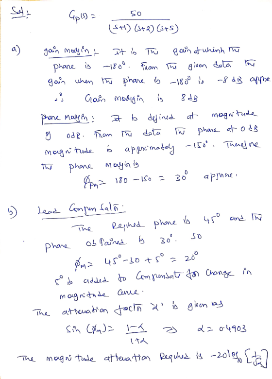
For the system shown in Figure 1, the plant transfer function is given by 50 Gp(s) = 1s + 1)(s + 2)(s+5) ( The frequenc...
Consider the transfer function of a DC motor given by G(s) = 1 / s(s+2) 3. Consider the transfer function of a DC motor...
 Consider the transfer function of a DC motor given by G(s) = 1 /
s(s+2)
3. Consider the transfer function of a DC motor given by 1 G(s) s (s2) The objective of this question is to consider the problem of control design for this DC motor, with the feedback control architecture shown in the figure below d(t r(t) e(t) e(t) C(s) G(s) Figure 4: A feedback control system (a) Find the magnitude and the phase of the frequency response...
Consider the transfer function of a DC motor given by G(s) = 1 /
s(s+2)
3. Consider the transfer function of a DC motor given by 1 G(s) s (s2) The objective of this question is to consider the problem of control design for this DC motor, with the feedback control architecture shown in the figure below d(t r(t) e(t) e(t) C(s) G(s) Figure 4: A feedback control system (a) Find the magnitude and the phase of the frequency response...
The transfer function of the given physical system is Gp(s)-1000 The physical system is controlle...
 The transfer function of the given physical system is Gp(s)-1000 The physical system is controlled with a unity-feedback system shown below, R(s) + Where Ge is the controller transfer function 3. Lead/Lag Compensator (a) Design a compensator such that the settling time of the compensated system T < 0.02 sec (Use 5% definition), and maximum overshoot of the compensated system is Mp 20%. Clearly explain all your steps. (b) Build a simulink model and use the compensator you designed above....
SS10. The unity-feedback system of Figure P11.1 with K (s +4) G (s) (s 2) (s 5) (s +12) is operat...
 SS10. The unity-feedback system of Figure P11.1 with K (s +4) G (s) (s 2) (s 5) (s +12) is operating with 20% overshoot. [Section: 114] a. Find the settling time. b. Find Kp c. Find the phase margin and the phase-margin frequency d. Using frequency response techniques, design a compensator that will yield a threefold improvement in Kp and a twofold reduction in settling time while keeping the overshoot at 20%.
SS10. The unity-feedback system of Figure P11.1 with...
SS10. The unity-feedback system of Figure P11.1 with K (s +4) G (s) (s 2) (s 5) (s +12) is operating with 20% overshoot. [Section: 114] a. Find the settling time. b. Find Kp c. Find the phase margin and the phase-margin frequency d. Using frequency response techniques, design a compensator that will yield a threefold improvement in Kp and a twofold reduction in settling time while keeping the overshoot at 20%.
SS10. The unity-feedback system of Figure P11.1 with...
14. The unity feedback system of Figure P1 1.1 with K(s+ 4) (s+2(s+5)(s+12) G(s) is operating...
 14. The unity feedback system of Figure P1 1.1 with K(s+ 4) (s+2(s+5)(s+12) G(s) is operating with 20% overshoot. [Section: 11.4 a. Find the settling time b. Find Kp c. Find the phase margin and the phase-margin frequency d. Using frequency response techniques, design a compensator that will yield a threefold improvement in Kp and a twofold reduction in settling time while keeping the overshoot at 20%.
urgent!! II Lag/lead Compensator Design A certain plant with unity feedback has the model given by GP(s) s(1 +0.1s) (1 0.2s) Design a phase-lag OR phase-lead compensator such that: 1. The steady-...
 urgent!!
II Lag/lead Compensator Design A certain plant with unity feedback has the model given by GP(s) s(1 +0.1s) (1 0.2s) Design a phase-lag OR phase-lead compensator such that: 1. The steady- state error with respect to a unit ramp input is no more than 0.01; 2. Phase margin is approximately 40
II Lag/lead Compensator Design A certain plant with unity feedback has the model given by GP(s) s(1 +0.1s) (1 0.2s) Design a phase-lag OR phase-lead compensator such that:...
urgent!!
II Lag/lead Compensator Design A certain plant with unity feedback has the model given by GP(s) s(1 +0.1s) (1 0.2s) Design a phase-lag OR phase-lead compensator such that: 1. The steady- state error with respect to a unit ramp input is no more than 0.01; 2. Phase margin is approximately 40
II Lag/lead Compensator Design A certain plant with unity feedback has the model given by GP(s) s(1 +0.1s) (1 0.2s) Design a phase-lag OR phase-lead compensator such that:...
Consider the system given below where K is a constant gain, Gp is the plant, and Ge is a compensator. The Bode Plots of a Gp is given below. Problem 1: Bode Diagram 20 2 40 -60 80 -100 90 135 180 a 2...
 Consider the system given below where K is a constant gain, Gp is the plant, and Ge is a compensator. The Bode Plots of a Gp is given below. Problem 1: Bode Diagram 20 2 40 -60 80 -100 90 135 180 a 225 270 101 10 Frequency (rad/s) 102 a. Looking at the low frequency behavior, determine its number of poles at origin. Explain. b. Looking at the high frequency behavior, determine the number of excess poles. Explain. C....
3. (28 pts.) The unity feedback system with K(5+3) G(s) = (s + 1)(s + 4)(s...
 3. (28 pts.) The unity feedback system with K(5+3) G(s) = (s + 1)(s + 4)(s + 10) is operating with 12% overshoot ({=0.56). (a) the root locus plot is below, find the settling time (b) find ko (c) using frequency response techniques, design a lead compensator that will yield a twofold improvement in K, and a twofold reduction in settling time while keeping the overshoot at 12%; the Bode plot is below using the margin command and using the...
For the given system above, determine the gain K that will give the system desired response below: Settling time of 5 seconds Peak time of 0.5 seconds The given plant has a transfer function of: Gp...
 For the given system above, determine the gain K that will give
the system desired response below:
Settling time of 5 seconds
Peak time of 0.5 seconds
The given plant has a transfer function of: Gp = (s + 4)/( (s +
1)*(s + 3) )
The controller has a transfer function of: Gc =
(s+27.75)/s
QUESTION 2 10 points Save Answer Y(S) R(s) Gc(s) Gp(s) For the given system above, determine the gain K that will give the system...
For the given system above, determine the gain K that will give
the system desired response below:
Settling time of 5 seconds
Peak time of 0.5 seconds
The given plant has a transfer function of: Gp = (s + 4)/( (s +
1)*(s + 3) )
The controller has a transfer function of: Gc =
(s+27.75)/s
QUESTION 2 10 points Save Answer Y(S) R(s) Gc(s) Gp(s) For the given system above, determine the gain K that will give the system...
The transfer function of the given physical system is 2500 Gp(s)-T-1000 Part 3 1. Frequency response (a) Draw the bode...
 The transfer function of the given physical system is 2500 Gp(s)-T-1000 Part 3 1. Frequency response (a) Draw the bode plot of open-loop transfer function when K (b) Use bode plot of open-loop transfer function to determine the type of system (do not use transfer function) (c) For what input the system will have constant steady-state error (d) for the unit input in item (c) calculate the constant steady-state error.(Use bode plot to calculate the error.) (e) Design a lead...
2. You are given the motor whose transfer function is shown in Figure 2(a). s) e(s) Amplifier Mot...
 Control system
2. You are given the motor whose transfer function is shown in Figure 2(a). s) e(s) Amplifier Motor C(s) 15 Tachometer Кр Figure 2 a) If this motor were the forward transfer function of a unity feedback system, calculate the percent overshoot and settling time that could be expected. b) You want to improve the closed-loop response. Since the motor constants cannot be changed and you cannot use a different motor, an amplifier and tachometer are inserted into...
Control system
2. You are given the motor whose transfer function is shown in Figure 2(a). s) e(s) Amplifier Motor C(s) 15 Tachometer Кр Figure 2 a) If this motor were the forward transfer function of a unity feedback system, calculate the percent overshoot and settling time that could be expected. b) You want to improve the closed-loop response. Since the motor constants cannot be changed and you cannot use a different motor, an amplifier and tachometer are inserted into...
 Consider the transfer function of a DC motor given by G(s) = 1 /
s(s+2)
3. Consider the transfer function of a DC motor given by 1 G(s) s (s2) The objective of this question is to consider the problem of control design for this DC motor, with the feedback control architecture shown in the figure below d(t r(t) e(t) e(t) C(s) G(s) Figure 4: A feedback control system (a) Find the magnitude and the phase of the frequency response...
Consider the transfer function of a DC motor given by G(s) = 1 /
s(s+2)
3. Consider the transfer function of a DC motor given by 1 G(s) s (s2) The objective of this question is to consider the problem of control design for this DC motor, with the feedback control architecture shown in the figure below d(t r(t) e(t) e(t) C(s) G(s) Figure 4: A feedback control system (a) Find the magnitude and the phase of the frequency response...
 The transfer function of the given physical system is Gp(s)-1000 The physical system is controlled with a unity-feedback system shown below, R(s) + Where Ge is the controller transfer function 3. Lead/Lag Compensator (a) Design a compensator such that the settling time of the compensated system T < 0.02 sec (Use 5% definition), and maximum overshoot of the compensated system is Mp 20%. Clearly explain all your steps. (b) Build a simulink model and use the compensator you designed above....
 SS10. The unity-feedback system of Figure P11.1 with K (s +4) G (s) (s 2) (s 5) (s +12) is operating with 20% overshoot. [Section: 114] a. Find the settling time. b. Find Kp c. Find the phase margin and the phase-margin frequency d. Using frequency response techniques, design a compensator that will yield a threefold improvement in Kp and a twofold reduction in settling time while keeping the overshoot at 20%.
SS10. The unity-feedback system of Figure P11.1 with...
SS10. The unity-feedback system of Figure P11.1 with K (s +4) G (s) (s 2) (s 5) (s +12) is operating with 20% overshoot. [Section: 114] a. Find the settling time. b. Find Kp c. Find the phase margin and the phase-margin frequency d. Using frequency response techniques, design a compensator that will yield a threefold improvement in Kp and a twofold reduction in settling time while keeping the overshoot at 20%.
SS10. The unity-feedback system of Figure P11.1 with...
 14. The unity feedback system of Figure P1 1.1 with K(s+ 4) (s+2(s+5)(s+12) G(s) is operating with 20% overshoot. [Section: 11.4 a. Find the settling time b. Find Kp c. Find the phase margin and the phase-margin frequency d. Using frequency response techniques, design a compensator that will yield a threefold improvement in Kp and a twofold reduction in settling time while keeping the overshoot at 20%.
 urgent!!
II Lag/lead Compensator Design A certain plant with unity feedback has the model given by GP(s) s(1 +0.1s) (1 0.2s) Design a phase-lag OR phase-lead compensator such that: 1. The steady- state error with respect to a unit ramp input is no more than 0.01; 2. Phase margin is approximately 40
II Lag/lead Compensator Design A certain plant with unity feedback has the model given by GP(s) s(1 +0.1s) (1 0.2s) Design a phase-lag OR phase-lead compensator such that:...
urgent!!
II Lag/lead Compensator Design A certain plant with unity feedback has the model given by GP(s) s(1 +0.1s) (1 0.2s) Design a phase-lag OR phase-lead compensator such that: 1. The steady- state error with respect to a unit ramp input is no more than 0.01; 2. Phase margin is approximately 40
II Lag/lead Compensator Design A certain plant with unity feedback has the model given by GP(s) s(1 +0.1s) (1 0.2s) Design a phase-lag OR phase-lead compensator such that:...
 Consider the system given below where K is a constant gain, Gp is the plant, and Ge is a compensator. The Bode Plots of a Gp is given below. Problem 1: Bode Diagram 20 2 40 -60 80 -100 90 135 180 a 225 270 101 10 Frequency (rad/s) 102 a. Looking at the low frequency behavior, determine its number of poles at origin. Explain. b. Looking at the high frequency behavior, determine the number of excess poles. Explain. C....
 3. (28 pts.) The unity feedback system with K(5+3) G(s) = (s + 1)(s + 4)(s + 10) is operating with 12% overshoot ({=0.56). (a) the root locus plot is below, find the settling time (b) find ko (c) using frequency response techniques, design a lead compensator that will yield a twofold improvement in K, and a twofold reduction in settling time while keeping the overshoot at 12%; the Bode plot is below using the margin command and using the...
 For the given system above, determine the gain K that will give
the system desired response below:
Settling time of 5 seconds
Peak time of 0.5 seconds
The given plant has a transfer function of: Gp = (s + 4)/( (s +
1)*(s + 3) )
The controller has a transfer function of: Gc =
(s+27.75)/s
QUESTION 2 10 points Save Answer Y(S) R(s) Gc(s) Gp(s) For the given system above, determine the gain K that will give the system...
For the given system above, determine the gain K that will give
the system desired response below:
Settling time of 5 seconds
Peak time of 0.5 seconds
The given plant has a transfer function of: Gp = (s + 4)/( (s +
1)*(s + 3) )
The controller has a transfer function of: Gc =
(s+27.75)/s
QUESTION 2 10 points Save Answer Y(S) R(s) Gc(s) Gp(s) For the given system above, determine the gain K that will give the system...
 The transfer function of the given physical system is 2500 Gp(s)-T-1000 Part 3 1. Frequency response (a) Draw the bode plot of open-loop transfer function when K (b) Use bode plot of open-loop transfer function to determine the type of system (do not use transfer function) (c) For what input the system will have constant steady-state error (d) for the unit input in item (c) calculate the constant steady-state error.(Use bode plot to calculate the error.) (e) Design a lead...
 Control system
2. You are given the motor whose transfer function is shown in Figure 2(a). s) e(s) Amplifier Motor C(s) 15 Tachometer Кр Figure 2 a) If this motor were the forward transfer function of a unity feedback system, calculate the percent overshoot and settling time that could be expected. b) You want to improve the closed-loop response. Since the motor constants cannot be changed and you cannot use a different motor, an amplifier and tachometer are inserted into...
Control system
2. You are given the motor whose transfer function is shown in Figure 2(a). s) e(s) Amplifier Motor C(s) 15 Tachometer Кр Figure 2 a) If this motor were the forward transfer function of a unity feedback system, calculate the percent overshoot and settling time that could be expected. b) You want to improve the closed-loop response. Since the motor constants cannot be changed and you cannot use a different motor, an amplifier and tachometer are inserted into...
Most questions answered within 3 hours.
-
9.) You are buying a car that cost $26,500. You make payments of
$412 each month...
asked 1 minute from now -
. Suppose a discrete random variable has probability
distribution
P(x) = .2 if x = 0...
asked 1 hour ago -
Problem #1
The area between Z = 0 and Z = 2.50
The area between Z...
asked 14 minutes ago -
Under the influence of its drive force, a snowmobile is moving
at a constant velocity along...
asked 1 hour ago -
Why do organizations decline? What steps can top
management take to halt, decline, and restore organizational...
asked 1 hour ago -
What mechanisms Drive speciation??
(I.e. what was Dawins theory on the orgin of species, and how...
asked 3 hours ago -
The manager at a car assembly plant believes that the mean
assembly time for a car...
asked 3 hours ago -
Which of the following is true of electron capture?
A) It decreases the nuclide's mass number...
asked 5 hours ago -
Assuming an efficiency of 43.10%, calculate the actual yield of
magnesium nitrate formed from 114.9 g...
asked 6 hours ago -
The highly pathogenic bacterium Clostridium
perfringens causes gangrene, a disease that results in the
destruction of...
asked 7 hours ago -
In the context of situation analysis, which of the following is
a category for analysis in...
asked 7 hours ago -
In a study of the gas phase decomposition of sulfuryl chloride
at 600 K SO2Cl2(g)SO2(g) +...
asked 7 hours ago